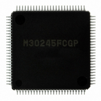
M30245FCGP#U1 Renesas Electronics America, M30245FCGP#U1 Datasheet - Page 81

M30245FCGP#U1
Manufacturer Part Number
M30245FCGP#U1
Description
IC M16C/24 MCU FLSH 128K 100LQFP
Manufacturer
Renesas Electronics America
Series
M16C™ M16C/20r
Datasheet
1.M30245FCGPU1.pdf
(268 pages)
Specifications of M30245FCGP#U1
Core Processor
M16C/60
Core Size
16-Bit
Speed
16MHz
Connectivity
I²C, SPI, SSI, UART/USART, USB
Peripherals
DMA, PWM, WDT
Number Of I /o
82
Program Memory Size
128KB (128K x 8)
Program Memory Type
FLASH
Ram Size
10K x 8
Voltage - Supply (vcc/vdd)
3 V ~ 3.6 V
Data Converters
A/D 8x10b
Oscillator Type
Internal
Operating Temperature
-20°C ~ 85°C
Package / Case
100-LQFP
Package
100LQFP
Family Name
R8C
Maximum Speed
16 MHz
Operating Supply Voltage
3.3 V
Data Bus Width
16 Bit
Number Of Programmable I/os
82
Interface Type
USB/UART/I2C/SPI
On-chip Adc
8-chx10-bit
Number Of Timers
5
Lead Free Status / RoHS Status
Lead free / RoHS Compliant
Eeprom Size
-
Available stocks
Company
Part Number
Manufacturer
Quantity
Price
- Current page: 81 of 268
- Download datasheet (3Mb)
M30245 Group
Rev.2.00
REJ03B0005-0200
Table 1.36. Endpoints 1-4 OUT buffer status
OUT_BUF_STS1
OUT Endpoint FIFO Flush
Interrupt Endpoints
A software flush causes the USB FCU to act as if a data set has been unloaded from the buffer. The user must only
set the flush bit when OUT_BUF_STS1 = 1, which indicates that one or two data sets have been received. When
there is one data set in the buffer, a flush causes the buffer to empty. When there are two data sets in the buffer, a
flush causes the older data set to be flushed out from the buffer. A flush also updates the buffer status flags of the
corresponding EPx OUT CSR.
The status of Endpoint 1-4 OUT buffers can be obtained from the two status bits of the EPx OUT CSR of the corre-
sponding endpoint as shown in Table 1.36.
Any endpoint can be used for interrupt transfers. For normal interrupt transfers, the interrupt transactions behave the
same as bulk transactions, i.e., no special setting is required.
The IN endpoints may be used to communicate rate feedback information for certain types of isochronous functions.
Setting the INTPT bit in the IN CSR register of the corresponding IN CSR enables this function. When the INTPT bit is
set, the data toggle bit changes after each packet is sent regardless of the presence or type of handshake that is
returned from the host.
The operation sequence for an IN endpoint used to communicate rate feedback information is listed in the following
steps.
1. Set single buffer mode for the endpoint in use;
2. Set INTPT bit of the IN CSR;
3. Load interrupt status information and set SET_IN_BUF_RDY bit in the IN CSR;
4. Repeat step 3 for all subsequent interrupt status updates.
When an interrupt endpoint is used for rate feedback, the device always has data to send back to the host, even if the
data conveys that everything is ‘fine’. Therefore, the device never NAKs an IN token from the host. The device always
sends out the data in the FIFO in response to an IN token regardless of the IN buffer status bits.
0
0
1
1
Oct 16, 2006
OUT_BUF_STS0
page 79 of 264
0
1
0
1
No data set in the OUT buffer
Single buffer mode:
Double buffer mode:
Single buffer mode:
Double buffer mode:
Single buffer mode:
Double buffer mode:
Buffer Status
N/A
N/A
N/A
One data set in the OUT buffer
One data set in the OUT buffer
Two data sets in the OUT buffer
Universal Serial Bus
Related parts for M30245FCGP#U1
Image
Part Number
Description
Manufacturer
Datasheet
Request
R

Part Number:
Description:
KIT STARTER FOR M16C/29
Manufacturer:
Renesas Electronics America
Datasheet:

Part Number:
Description:
KIT STARTER FOR R8C/2D
Manufacturer:
Renesas Electronics America
Datasheet:

Part Number:
Description:
R0K33062P STARTER KIT
Manufacturer:
Renesas Electronics America
Datasheet:

Part Number:
Description:
KIT STARTER FOR R8C/23 E8A
Manufacturer:
Renesas Electronics America
Datasheet:

Part Number:
Description:
KIT STARTER FOR R8C/25
Manufacturer:
Renesas Electronics America
Datasheet:

Part Number:
Description:
KIT STARTER H8S2456 SHARPE DSPLY
Manufacturer:
Renesas Electronics America
Datasheet:

Part Number:
Description:
KIT STARTER FOR R8C38C
Manufacturer:
Renesas Electronics America
Datasheet:

Part Number:
Description:
KIT STARTER FOR R8C35C
Manufacturer:
Renesas Electronics America
Datasheet:

Part Number:
Description:
KIT STARTER FOR R8CL3AC+LCD APPS
Manufacturer:
Renesas Electronics America
Datasheet:

Part Number:
Description:
KIT STARTER FOR RX610
Manufacturer:
Renesas Electronics America
Datasheet:

Part Number:
Description:
KIT STARTER FOR R32C/118
Manufacturer:
Renesas Electronics America
Datasheet:

Part Number:
Description:
KIT DEV RSK-R8C/26-29
Manufacturer:
Renesas Electronics America
Datasheet:

Part Number:
Description:
KIT STARTER FOR SH7124
Manufacturer:
Renesas Electronics America
Datasheet:

Part Number:
Description:
KIT STARTER FOR H8SX/1622
Manufacturer:
Renesas Electronics America
Datasheet:


