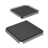
D12674RVFQ33D Renesas Electronics America, D12674RVFQ33D Datasheet - Page 18

D12674RVFQ33D
Manufacturer Part Number
D12674RVFQ33D
Description
MCU 3V 0K I-TEMP 144-QFP
Manufacturer
Renesas Electronics America
Series
H8® H8S/2600r
Datasheet
1.D12674RVFQ33V.pdf
(981 pages)
Specifications of D12674RVFQ33D
Core Processor
H8S/2600
Core Size
16-Bit
Speed
33MHz
Connectivity
IrDA, SCI
Peripherals
DMA, POR, PWM, WDT
Number Of I /o
103
Program Memory Type
ROMless
Ram Size
32K x 8
Voltage - Supply (vcc/vdd)
3 V ~ 3.6 V
Data Converters
A/D 12x10b; D/A 4x8b
Oscillator Type
Internal
Operating Temperature
-40°C ~ 85°C
Package / Case
144-LQFP
Lead Free Status / RoHS Status
Contains lead / RoHS non-compliant
Eeprom Size
-
Program Memory Size
-
Other names
HD6412674RVFQ33D
HD6412674RVFQ33D
HD6412674RVFQ33D
Available stocks
Company
Part Number
Manufacturer
Quantity
Price
Company:
Part Number:
D12674RVFQ33DV
Manufacturer:
Renesas Electronics America
Quantity:
10 000
- Current page: 18 of 981
- Download datasheet (6Mb)
6.4
6.5
6.6
6.7
Rev. 3.00 Mar 17, 2006 page xvi of l
6.3.7
6.3.8
6.3.9
6.3.10 Refresh Control Register (REFCR) ..................................................................... 149
6.3.11 Refresh Timer Counter (RTCNT)........................................................................ 152
6.3.12 Refresh Time Constant Register (RTCOR) ......................................................... 152
Bus Control ....................................................................................................................... 152
6.4.1
6.4.2
6.4.3
6.4.4
Basic Bus Interface ........................................................................................................... 158
6.5.1
6.5.2
6.5.3
6.5.4
6.5.5
6.5.6
DRAM Interface ............................................................................................................... 173
6.6.1
6.6.2
6.6.3
6.6.4
6.6.5
6.6.6
6.6.7
6.6.8
6.6.9
6.6.10 Byte Access Control ............................................................................................ 184
6.6.11 Burst Operation.................................................................................................... 185
6.6.12 Refresh Control.................................................................................................... 190
6.6.13 DMAC and EXDMAC Single Address Transfer Mode and DRAM Interface.... 195
Synchronous DRAM Interface.......................................................................................... 198
6.7.1
6.7.2
6.7.3
6.7.4
6.7.5
6.7.6
6.7.7
6.7.8
Bus Control Register (BCR) ................................................................................ 136
DRAM Control Register (DRAMCR) ................................................................. 138
DRAM Access Control Register (DRACCR) ...................................................... 144
Area Division ....................................................................................................... 152
Bus Specifications................................................................................................ 154
Memory Interfaces ............................................................................................... 156
Chip Select Signals .............................................................................................. 157
Data Size and Data Alignment............................................................................. 158
Valid Strobes........................................................................................................ 160
Basic Operation Timing ....................................................................................... 160
Wait Control ........................................................................................................ 169
Read Strobe (RD) Timing .................................................................................... 170
Extension of Chip Select (CS) Assertion Period.................................................. 171
Setting DRAM Space........................................................................................... 173
Address Multiplexing........................................................................................... 173
Data Bus............................................................................................................... 174
Pins Used for DRAM Interface............................................................................ 175
Basic Timing........................................................................................................ 176
Column Address Output Cycle Control ............................................................... 177
Row Address Output State Control...................................................................... 178
Precharge State Control ....................................................................................... 180
Wait Control ........................................................................................................ 181
Setting Continuous Synchronous DRAM Space.................................................. 198
Address Multiplexing........................................................................................... 199
Data Bus............................................................................................................... 200
Pins Used for Synchronous DRAM Interface ...................................................... 200
Synchronous DRAM Clock ................................................................................. 202
Basic Operation Timing ....................................................................................... 202
CAS Latency Control........................................................................................... 204
Row Address Output State Control...................................................................... 206
Related parts for D12674RVFQ33D
Image
Part Number
Description
Manufacturer
Datasheet
Request
R

Part Number:
Description:
CCD Vertical Clock Driver
Manufacturer:
Sony Corporation
Datasheet:

Part Number:
Description:
KIT STARTER FOR M16C/29
Manufacturer:
Renesas Electronics America
Datasheet:

Part Number:
Description:
KIT STARTER FOR R8C/2D
Manufacturer:
Renesas Electronics America
Datasheet:

Part Number:
Description:
R0K33062P STARTER KIT
Manufacturer:
Renesas Electronics America
Datasheet:

Part Number:
Description:
KIT STARTER FOR R8C/23 E8A
Manufacturer:
Renesas Electronics America
Datasheet:

Part Number:
Description:
KIT STARTER FOR R8C/25
Manufacturer:
Renesas Electronics America
Datasheet:

Part Number:
Description:
KIT STARTER H8S2456 SHARPE DSPLY
Manufacturer:
Renesas Electronics America
Datasheet:

Part Number:
Description:
KIT STARTER FOR R8C38C
Manufacturer:
Renesas Electronics America
Datasheet:

Part Number:
Description:
KIT STARTER FOR R8C35C
Manufacturer:
Renesas Electronics America
Datasheet:

Part Number:
Description:
KIT STARTER FOR R8CL3AC+LCD APPS
Manufacturer:
Renesas Electronics America
Datasheet:

Part Number:
Description:
KIT STARTER FOR RX610
Manufacturer:
Renesas Electronics America
Datasheet:

Part Number:
Description:
KIT STARTER FOR R32C/118
Manufacturer:
Renesas Electronics America
Datasheet:

Part Number:
Description:
KIT DEV RSK-R8C/26-29
Manufacturer:
Renesas Electronics America
Datasheet:

Part Number:
Description:
KIT STARTER FOR SH7124
Manufacturer:
Renesas Electronics America
Datasheet:

Part Number:
Description:
KIT STARTER FOR H8SX/1622
Manufacturer:
Renesas Electronics America
Datasheet:


