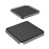
D12674RVFQ33D Renesas Electronics America, D12674RVFQ33D Datasheet - Page 973

D12674RVFQ33D
Manufacturer Part Number
D12674RVFQ33D
Description
MCU 3V 0K I-TEMP 144-QFP
Manufacturer
Renesas Electronics America
Series
H8® H8S/2600r
Datasheet
1.D12674RVFQ33V.pdf
(981 pages)
Specifications of D12674RVFQ33D
Core Processor
H8S/2600
Core Size
16-Bit
Speed
33MHz
Connectivity
IrDA, SCI
Peripherals
DMA, POR, PWM, WDT
Number Of I /o
103
Program Memory Type
ROMless
Ram Size
32K x 8
Voltage - Supply (vcc/vdd)
3 V ~ 3.6 V
Data Converters
A/D 12x10b; D/A 4x8b
Oscillator Type
Internal
Operating Temperature
-40°C ~ 85°C
Package / Case
144-LQFP
Lead Free Status / RoHS Status
Contains lead / RoHS non-compliant
Eeprom Size
-
Program Memory Size
-
Other names
HD6412674RVFQ33D
HD6412674RVFQ33D
HD6412674RVFQ33D
Available stocks
Company
Part Number
Manufacturer
Quantity
Price
Company:
Part Number:
D12674RVFQ33DV
Manufacturer:
Renesas Electronics America
Quantity:
10 000
- Current page: 973 of 981
- Download datasheet (6Mb)
16-Bit Timer Pulse Unit.......................... 521
8-Bit Timers............................................ 627
A/D Converter ........................................ 741
Address Space........................................... 28
Addressing Modes .................................... 48
Buffer Operation ................................. 566
Cascaded Operation ............................ 570
Free-running count operation.............. 560
Input Capture Function ....................... 563
periodic count operation ..................... 560
Phase Counting Mode......................... 577
PWM Modes....................................... 572
Synchronous Operation....................... 564
toggle output ....................................... 562
Waveform Output by Compare Match 561
16-Bit Counter Mode .......................... 641
Compare Match Count Mode.............. 641
Operation with Cascaded Connection. 641
Pulse Output........................................ 636
TCNT Incrementation Timing ............ 637
Toggle output...................................... 646
Conversion Time................................. 753
DTC Activation................................... 585
External Trigger .................................. 756
Scan Mode .......................................... 752
Single Mode........................................ 752
Absolute Address.................................. 50
Immediate ............................................. 51
Memory Indirect ................................... 51
Program-Counter Relative .................... 51
Register Direct ...................................... 49
Register Indirect.................................... 49
Register Indirect with Displacement..... 49
Register indirect with post-increment ... 50
Register indirect with pre-decrement .... 50
Index
Bcc ......................................................37, 45
Bus Controller .........................................121
Clock Pulse Generator.............................811
Condition Field .........................................47
Condition-Code Register (CCR) ...............32
CPU Operating Modes ..............................24
D/A Converter.........................................763
data direction register..............................427
data register .............................................427
Data Transfer Controller .........................401
Auto Refreshing ..................................218
Basic Bus Interface .............................158
Basic Operation Timing ..............160, 202
Basic Timing .......................................229
Burst ROM Interface...........................229
Bus Arbitration....................................255
Bus Release .........................................250
Chip Select (CS) Assertion Period
Data Size and Data Alignment ............158
DRAM Interface..................................173
Idle Cycle ............................................232
Read Strobe (RD) Timing ...................170
Self-Refreshing ...................................220
Synchronous DRAM Interface............198
Valid Strobes.......................................160
Wait Control........................................169
Write Data Buffer Function.................249
PLL Circuit .........................................816
Advanced Mode ....................................26
Normal Mode ..................................24, 25
Activation by Software ...............416, 420
Block Transfer Mode ..........................414
Chain Transfer.............................415, 422
Chain Transfer when Counter = 0 .......423
DTC Vector Table...............................408
Rev. 3.00 Mar 17, 2006 page 921 of 926
Extension States ..............................155
REJ09B0283-0300
Index
Related parts for D12674RVFQ33D
Image
Part Number
Description
Manufacturer
Datasheet
Request
R

Part Number:
Description:
CCD Vertical Clock Driver
Manufacturer:
Sony Corporation
Datasheet:

Part Number:
Description:
KIT STARTER FOR M16C/29
Manufacturer:
Renesas Electronics America
Datasheet:

Part Number:
Description:
KIT STARTER FOR R8C/2D
Manufacturer:
Renesas Electronics America
Datasheet:

Part Number:
Description:
R0K33062P STARTER KIT
Manufacturer:
Renesas Electronics America
Datasheet:

Part Number:
Description:
KIT STARTER FOR R8C/23 E8A
Manufacturer:
Renesas Electronics America
Datasheet:

Part Number:
Description:
KIT STARTER FOR R8C/25
Manufacturer:
Renesas Electronics America
Datasheet:

Part Number:
Description:
KIT STARTER H8S2456 SHARPE DSPLY
Manufacturer:
Renesas Electronics America
Datasheet:

Part Number:
Description:
KIT STARTER FOR R8C38C
Manufacturer:
Renesas Electronics America
Datasheet:

Part Number:
Description:
KIT STARTER FOR R8C35C
Manufacturer:
Renesas Electronics America
Datasheet:

Part Number:
Description:
KIT STARTER FOR R8CL3AC+LCD APPS
Manufacturer:
Renesas Electronics America
Datasheet:

Part Number:
Description:
KIT STARTER FOR RX610
Manufacturer:
Renesas Electronics America
Datasheet:

Part Number:
Description:
KIT STARTER FOR R32C/118
Manufacturer:
Renesas Electronics America
Datasheet:

Part Number:
Description:
KIT DEV RSK-R8C/26-29
Manufacturer:
Renesas Electronics America
Datasheet:

Part Number:
Description:
KIT STARTER FOR SH7124
Manufacturer:
Renesas Electronics America
Datasheet:

Part Number:
Description:
KIT STARTER FOR H8SX/1622
Manufacturer:
Renesas Electronics America
Datasheet:


