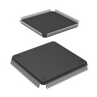
D12674RVFQ33D Renesas Electronics America, D12674RVFQ33D Datasheet - Page 49

D12674RVFQ33D
Manufacturer Part Number
D12674RVFQ33D
Description
MCU 3V 0K I-TEMP 144-QFP
Manufacturer
Renesas Electronics America
Series
H8® H8S/2600r
Datasheet
1.D12674RVFQ33V.pdf
(981 pages)
Specifications of D12674RVFQ33D
Core Processor
H8S/2600
Core Size
16-Bit
Speed
33MHz
Connectivity
IrDA, SCI
Peripherals
DMA, POR, PWM, WDT
Number Of I /o
103
Program Memory Type
ROMless
Ram Size
32K x 8
Voltage - Supply (vcc/vdd)
3 V ~ 3.6 V
Data Converters
A/D 12x10b; D/A 4x8b
Oscillator Type
Internal
Operating Temperature
-40°C ~ 85°C
Package / Case
144-LQFP
Lead Free Status / RoHS Status
Contains lead / RoHS non-compliant
Eeprom Size
-
Program Memory Size
-
Other names
HD6412674RVFQ33D
HD6412674RVFQ33D
HD6412674RVFQ33D
Available stocks
Company
Part Number
Manufacturer
Quantity
Price
Company:
Part Number:
D12674RVFQ33DV
Manufacturer:
Renesas Electronics America
Quantity:
10 000
- Current page: 49 of 981
- Download datasheet (6Mb)
Table 11.28 Register Combinations in Buffer Operation........................................................... 567
Table 11.29 Cascaded Combinations ......................................................................................... 570
Table 11.30 PWM Output Registers and Output Pins................................................................ 573
Table 11.31 Clock Input Pins in Phase Counting Mode............................................................. 577
Table 11.32 Up/Down-Count Conditions in Phase Counting Mode 1 ....................................... 578
Table 11.33 Up/Down-Count Conditions in Phase Counting Mode 2 ....................................... 579
Table 11.34 Up/Down-Count Conditions in Phase Counting Mode 3 ....................................... 580
Table 11.35 Up/Down-Count Conditions in Phase Counting Mode 4 ....................................... 581
Table 11.36 TPU Interrupts........................................................................................................ 584
Section 12 Programmable Pulse Generator (PPG)
Table 12.1
Section 13 8-Bit Timers (TMR)
Table 13.1
Table 13.2
Table 13.3
Table 13.4
Table 13.5
Section 14 Watchdog Timer
Table 14.1
Table 14.2
Section 15 Serial Communication Interface (SCI, IrDA)
Table 15.1
Table 15.2
Table 15.3
Table 15.3
Table 15.3
Table 15.3
Table 15.4
Table 15.5
Table 15.6
Table 15.7
Table 15.8
Table 15.9
Table 15.10 Serial Transfer Formats (Asynchronous Mode) ..................................................... 692
Table 15.11 SSR Status Flags and Receive Data Handling........................................................ 699
Pin Configuration ................................................................................................... 607
Pin Configuration ................................................................................................... 629
Clock Input to TCNT and Count Condition ........................................................... 632
8-Bit Timer Interrupt Sources ................................................................................ 642
Timer Output Priorities .......................................................................................... 646
Switching of Internal Clock and TCNT Operation ................................................ 647
Pin configuration .................................................................................................... 650
WDT Interrupt Source............................................................................................ 656
Pin Configuration ................................................................................................... 664
Relationships between N Setting in BRR and Bit Rate B ...................................... 679
BRR Settings for Various Bit Rates (Asynchronous Mode) (1)............................. 680
BRR Settings for Various Bit Rates (Asynchronous Mode) (2)............................. 681
BRR Settings for Various Bit Rates (Asynchronous Mode) (3)............................. 682
BRR Settings for Various Bit Rates (Asynchronous Mode) (4)............................. 683
Maximum Bit Rate for Each Frequency (Asynchronous Mode)............................ 684
Maximum Bit Rate with External Clock Input (Asynchronous Mode).................. 684
BRR Settings for Various Bit Rates (Clocked Synchronous Mode) ...................... 685
Maximum Bit Rate with External Clock Input (Clocked Synchronous Mode)...... 686
Examples of Bit Rate for Various BRR Settings (Smart Card Interface Mode)
(when n = 0 and S = 372) ....................................................................................... 687
Maximum Bit Rate at Various Frequencies (Smart Card Interface Mode)
(when S = 372) ....................................................................................................... 687
Rev. 3.00 Mar 17, 2006 page xlvii of l
Related parts for D12674RVFQ33D
Image
Part Number
Description
Manufacturer
Datasheet
Request
R

Part Number:
Description:
CCD Vertical Clock Driver
Manufacturer:
Sony Corporation
Datasheet:

Part Number:
Description:
KIT STARTER FOR M16C/29
Manufacturer:
Renesas Electronics America
Datasheet:

Part Number:
Description:
KIT STARTER FOR R8C/2D
Manufacturer:
Renesas Electronics America
Datasheet:

Part Number:
Description:
R0K33062P STARTER KIT
Manufacturer:
Renesas Electronics America
Datasheet:

Part Number:
Description:
KIT STARTER FOR R8C/23 E8A
Manufacturer:
Renesas Electronics America
Datasheet:

Part Number:
Description:
KIT STARTER FOR R8C/25
Manufacturer:
Renesas Electronics America
Datasheet:

Part Number:
Description:
KIT STARTER H8S2456 SHARPE DSPLY
Manufacturer:
Renesas Electronics America
Datasheet:

Part Number:
Description:
KIT STARTER FOR R8C38C
Manufacturer:
Renesas Electronics America
Datasheet:

Part Number:
Description:
KIT STARTER FOR R8C35C
Manufacturer:
Renesas Electronics America
Datasheet:

Part Number:
Description:
KIT STARTER FOR R8CL3AC+LCD APPS
Manufacturer:
Renesas Electronics America
Datasheet:

Part Number:
Description:
KIT STARTER FOR RX610
Manufacturer:
Renesas Electronics America
Datasheet:

Part Number:
Description:
KIT STARTER FOR R32C/118
Manufacturer:
Renesas Electronics America
Datasheet:

Part Number:
Description:
KIT DEV RSK-R8C/26-29
Manufacturer:
Renesas Electronics America
Datasheet:

Part Number:
Description:
KIT STARTER FOR SH7124
Manufacturer:
Renesas Electronics America
Datasheet:

Part Number:
Description:
KIT STARTER FOR H8SX/1622
Manufacturer:
Renesas Electronics America
Datasheet:


