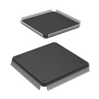
D12674RVFQ33D Renesas Electronics America, D12674RVFQ33D Datasheet - Page 19

D12674RVFQ33D
Manufacturer Part Number
D12674RVFQ33D
Description
MCU 3V 0K I-TEMP 144-QFP
Manufacturer
Renesas Electronics America
Series
H8® H8S/2600r
Datasheet
1.D12674RVFQ33V.pdf
(981 pages)
Specifications of D12674RVFQ33D
Core Processor
H8S/2600
Core Size
16-Bit
Speed
33MHz
Connectivity
IrDA, SCI
Peripherals
DMA, POR, PWM, WDT
Number Of I /o
103
Program Memory Type
ROMless
Ram Size
32K x 8
Voltage - Supply (vcc/vdd)
3 V ~ 3.6 V
Data Converters
A/D 12x10b; D/A 4x8b
Oscillator Type
Internal
Operating Temperature
-40°C ~ 85°C
Package / Case
144-LQFP
Lead Free Status / RoHS Status
Contains lead / RoHS non-compliant
Eeprom Size
-
Program Memory Size
-
Other names
HD6412674RVFQ33D
HD6412674RVFQ33D
HD6412674RVFQ33D
Available stocks
Company
Part Number
Manufacturer
Quantity
Price
Company:
Part Number:
D12674RVFQ33DV
Manufacturer:
Renesas Electronics America
Quantity:
10 000
- Current page: 19 of 981
- Download datasheet (6Mb)
6.8
6.9
6.10 Write Data Buffer Function .............................................................................................. 249
6.11 Bus Release....................................................................................................................... 250
6.12 Bus Arbitration.................................................................................................................. 255
6.13 Bus Controller Operation in Reset .................................................................................... 257
6.14 Usage Notes ...................................................................................................................... 257
Section 7 DMA Controller (DMAC)
7.1
7.2
7.3
6.7.9
6.7.10 Bus Cycle Control in Write Cycle ....................................................................... 210
6.7.11 Byte Access Control ............................................................................................ 211
6.7.12 Burst Operation.................................................................................................... 214
6.7.13 Refresh Control.................................................................................................... 217
6.7.14 Mode Register Setting of Synchronous DRAM................................................... 223
6.7.15 DMAC and EXDMAC Single Address Transfer Mode and Synchronous
Burst ROM Interface......................................................................................................... 229
6.8.1
6.8.2
6.8.3
Idle Cycle .......................................................................................................................... 232
6.9.1
6.9.2
6.11.1 Operation ............................................................................................................. 251
6.11.2 Pin States in External Bus Released State............................................................ 252
6.11.3 Transition Timing ................................................................................................ 253
6.12.1 Operation ............................................................................................................. 255
6.12.2 Bus Transfer Timing ............................................................................................ 255
6.14.1 External Bus Release Function and All-Module-Clocks-Stopped Mode............. 257
6.14.2 External Bus Release Function and Software Standby ........................................ 257
6.14.3 External Bus Release Function and CBR Refreshing/Auto Refreshing............... 258
6.14.4 BREQO Output Timing ....................................................................................... 258
6.14.5 Notes on Usage of the Synchronous DRAM ....................................................... 258
Features ............................................................................................................................. 259
Input/Output Pins .............................................................................................................. 261
Register Descriptions ........................................................................................................ 261
7.3.1
7.3.2
7.3.3
7.3.4
7.3.5
7.3.6
Precharge State Count.......................................................................................... 208
DRAM Interface .................................................................................................. 224
Basic Timing........................................................................................................ 229
Wait Control ........................................................................................................ 231
Write Access ........................................................................................................ 231
Operation ............................................................................................................. 232
Pin States in Idle Cycle ........................................................................................ 249
Memory Address Registers (MARA and MARB) ............................................... 263
I/O Address Registers (IOARA and IOARB) ...................................................... 263
Execute Transfer Count Registers (ETCRA and ETCRB) .................................. 264
DMA Control Registers (DMACRA and DMACRB) ......................................... 265
DMA Band Control Registers H and L (DMABCRH and DMABCRL)............. 272
DMA Write Enable Register (DMAWER) .......................................................... 283
............................................................................. 259
Rev. 3.00 Mar 17, 2006 page xvii of l
Related parts for D12674RVFQ33D
Image
Part Number
Description
Manufacturer
Datasheet
Request
R

Part Number:
Description:
CCD Vertical Clock Driver
Manufacturer:
Sony Corporation
Datasheet:

Part Number:
Description:
KIT STARTER FOR M16C/29
Manufacturer:
Renesas Electronics America
Datasheet:

Part Number:
Description:
KIT STARTER FOR R8C/2D
Manufacturer:
Renesas Electronics America
Datasheet:

Part Number:
Description:
R0K33062P STARTER KIT
Manufacturer:
Renesas Electronics America
Datasheet:

Part Number:
Description:
KIT STARTER FOR R8C/23 E8A
Manufacturer:
Renesas Electronics America
Datasheet:

Part Number:
Description:
KIT STARTER FOR R8C/25
Manufacturer:
Renesas Electronics America
Datasheet:

Part Number:
Description:
KIT STARTER H8S2456 SHARPE DSPLY
Manufacturer:
Renesas Electronics America
Datasheet:

Part Number:
Description:
KIT STARTER FOR R8C38C
Manufacturer:
Renesas Electronics America
Datasheet:

Part Number:
Description:
KIT STARTER FOR R8C35C
Manufacturer:
Renesas Electronics America
Datasheet:

Part Number:
Description:
KIT STARTER FOR R8CL3AC+LCD APPS
Manufacturer:
Renesas Electronics America
Datasheet:

Part Number:
Description:
KIT STARTER FOR RX610
Manufacturer:
Renesas Electronics America
Datasheet:

Part Number:
Description:
KIT STARTER FOR R32C/118
Manufacturer:
Renesas Electronics America
Datasheet:

Part Number:
Description:
KIT DEV RSK-R8C/26-29
Manufacturer:
Renesas Electronics America
Datasheet:

Part Number:
Description:
KIT STARTER FOR SH7124
Manufacturer:
Renesas Electronics America
Datasheet:

Part Number:
Description:
KIT STARTER FOR H8SX/1622
Manufacturer:
Renesas Electronics America
Datasheet:


