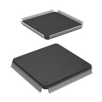
D12674RVFQ33D Renesas Electronics America, D12674RVFQ33D Datasheet - Page 43

D12674RVFQ33D
Manufacturer Part Number
D12674RVFQ33D
Description
MCU 3V 0K I-TEMP 144-QFP
Manufacturer
Renesas Electronics America
Series
H8® H8S/2600r
Datasheet
1.D12674RVFQ33V.pdf
(981 pages)
Specifications of D12674RVFQ33D
Core Processor
H8S/2600
Core Size
16-Bit
Speed
33MHz
Connectivity
IrDA, SCI
Peripherals
DMA, POR, PWM, WDT
Number Of I /o
103
Program Memory Type
ROMless
Ram Size
32K x 8
Voltage - Supply (vcc/vdd)
3 V ~ 3.6 V
Data Converters
A/D 12x10b; D/A 4x8b
Oscillator Type
Internal
Operating Temperature
-40°C ~ 85°C
Package / Case
144-LQFP
Lead Free Status / RoHS Status
Contains lead / RoHS non-compliant
Eeprom Size
-
Program Memory Size
-
Other names
HD6412674RVFQ33D
HD6412674RVFQ33D
HD6412674RVFQ33D
Available stocks
Company
Part Number
Manufacturer
Quantity
Price
Company:
Part Number:
D12674RVFQ33DV
Manufacturer:
Renesas Electronics America
Quantity:
10 000
- Current page: 43 of 981
- Download datasheet (6Mb)
Figure 16.3
Figure 16.4
Figure 16.5
Figure 16.6
Figure 16.7
Figure 16.8
Section 17 D/A Converter
Figure 17.1
Figure 17.2
Section 19 Flash Memory (F-ZTAT Version)
Figure 19.1
Figure 19.2
Figure 19.3
Figure 19.4
Figure 19.5
Figure 19.6
Figure 19.7
Figure 19.8
Figure 19.9
Figure 19.10 Program/Program-Verify Flowchart .................................................................... 797
Figure 19.11 Erase/Erase-Verify Flowchart.............................................................................. 799
Figure 19.12 Power-On/Off Timing (H8S/2678 Group)........................................................... 804
Figure 19.13 Power-On/Off Timing (H8S/2678R Group) ........................................................ 805
Figure 19.14 Mode Transition Timing
Section 20 Masked ROM
Figure 20.1
Figure 20.2
Figure 20.3
Section 21 Clock Pulse Generator
Figure 21.1
Figure 21.2
Figure 21.3
Figure 21.4
Figure 21.5
Figure 21.6
Figure 21.7
External Trigger Input Timing............................................................................. 756
A/D Conversion Accuracy Definitions ................................................................ 758
A/D Conversion Accuracy Definitions ................................................................ 758
Example of Analog Input Circuit......................................................................... 759
Example of Analog Input Protection Circuit ....................................................... 761
Analog Input Pin Equivalent Circuit.................................................................... 762
Block Diagram of D/A Converter ........................................................................ 764
Example of D/A Converter Operation ................................................................. 770
Flash Memory State Transitions .......................................................................... 775
Boot Mode ........................................................................................................... 776
User Program Mode............................................................................................. 777
384-kbyte Flash Memory Block Configuration (Modes 3, 4, and 7) ................... 779
256-kbyte Flash Memory Block Configuration (Modes 4, 7, 10, and 11) ........... 780
Programming/Erasing Flowchart Example in User Program Mode..................... 793
Flowchart for Flash Memory Emulation in RAM................................................ 794
Example of RAM Overlap Operation .................................................................. 795
(Example: Boot Mode
Block Diagram of 256-kbyte Masked ROM (HD6432676)................................. 809
Block Diagram of 128-kbyte Masked ROM (HD6432675)................................. 809
Block Diagram of 64-kbyte Masked ROM (HD6432673)................................... 810
Block Diagram of Clock Pulse Generator............................................................ 811
Connection of Crystal Resonator (Example) ....................................................... 814
Crystal Resonator Equivalent Circuit................................................................... 814
External Clock Input (Examples)......................................................................... 815
External Clock Input Timing ............................................................................... 816
Note on Board Design for Oscillation Circuit...................................................... 818
Recommended External Circuitry for PLL Circuit .............................................. 818
Block Diagram of Flash Memory ....................................................................... 774
User Mode
User Program Mode) .......................... 806
Rev. 3.00 Mar 17, 2006 page xli of l
Related parts for D12674RVFQ33D
Image
Part Number
Description
Manufacturer
Datasheet
Request
R

Part Number:
Description:
CCD Vertical Clock Driver
Manufacturer:
Sony Corporation
Datasheet:

Part Number:
Description:
KIT STARTER FOR M16C/29
Manufacturer:
Renesas Electronics America
Datasheet:

Part Number:
Description:
KIT STARTER FOR R8C/2D
Manufacturer:
Renesas Electronics America
Datasheet:

Part Number:
Description:
R0K33062P STARTER KIT
Manufacturer:
Renesas Electronics America
Datasheet:

Part Number:
Description:
KIT STARTER FOR R8C/23 E8A
Manufacturer:
Renesas Electronics America
Datasheet:

Part Number:
Description:
KIT STARTER FOR R8C/25
Manufacturer:
Renesas Electronics America
Datasheet:

Part Number:
Description:
KIT STARTER H8S2456 SHARPE DSPLY
Manufacturer:
Renesas Electronics America
Datasheet:

Part Number:
Description:
KIT STARTER FOR R8C38C
Manufacturer:
Renesas Electronics America
Datasheet:

Part Number:
Description:
KIT STARTER FOR R8C35C
Manufacturer:
Renesas Electronics America
Datasheet:

Part Number:
Description:
KIT STARTER FOR R8CL3AC+LCD APPS
Manufacturer:
Renesas Electronics America
Datasheet:

Part Number:
Description:
KIT STARTER FOR RX610
Manufacturer:
Renesas Electronics America
Datasheet:

Part Number:
Description:
KIT STARTER FOR R32C/118
Manufacturer:
Renesas Electronics America
Datasheet:

Part Number:
Description:
KIT DEV RSK-R8C/26-29
Manufacturer:
Renesas Electronics America
Datasheet:

Part Number:
Description:
KIT STARTER FOR SH7124
Manufacturer:
Renesas Electronics America
Datasheet:

Part Number:
Description:
KIT STARTER FOR H8SX/1622
Manufacturer:
Renesas Electronics America
Datasheet:


