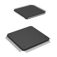
HD64F2239TF20I Renesas Electronics America, HD64F2239TF20I Datasheet - Page 27

HD64F2239TF20I
Manufacturer Part Number
HD64F2239TF20I
Description
MCU 3V 384K I-TEMP 100-TQFP
Manufacturer
Renesas Electronics America
Series
H8® H8S/2200r
Datasheet
1.DF2238RFA6V.pdf
(1048 pages)
Specifications of HD64F2239TF20I
Core Processor
H8S/2000
Core Size
16-Bit
Speed
20MHz
Connectivity
I²C, SCI, SmartCard
Peripherals
DMA, POR, PWM, WDT
Number Of I /o
72
Program Memory Size
384KB (384K x 8)
Program Memory Type
FLASH
Ram Size
32K x 8
Voltage - Supply (vcc/vdd)
2.7 V ~ 3.6 V
Data Converters
A/D 8x10b; D/A 2x8b
Oscillator Type
Internal
Operating Temperature
-40°C ~ 85°C
Package / Case
100-TQFP, 100-VQFP
Lead Free Status / RoHS Status
Contains lead / RoHS non-compliant
Eeprom Size
-
Available stocks
Company
Part Number
Manufacturer
Quantity
Price
Company:
Part Number:
HD64F2239TF20I
Manufacturer:
Renesas Electronics America
Quantity:
10 000
- Current page: 27 of 1048
- Download datasheet (6Mb)
7.11 Resets and the Bus Controller ...........................................................................................201
Section 8 DMA Controller (DMAC) ................................................................ 203
8.1
8.2
8.3
8.4
8.5
8.6
8.7
7.10.1 Operation .............................................................................................................199
7.10.2 Bus Transfer Timing ............................................................................................200
7.10.3 External Bus Release Usage Note........................................................................200
Features .............................................................................................................................203
Input/Output Pins .............................................................................................................. 205
Register Descriptions ........................................................................................................205
8.3.1
8.3.2
8.3.3
8.3.4
8.3.5
8.3.6
8.3.7
Activation Sources ............................................................................................................231
8.4.1
8.4.2
8.4.3
Operation...........................................................................................................................234
8.5.1
8.5.2
8.5.3
8.5.4
8.5.5
8.5.6
8.5.7
8.5.8
8.5.9
8.5.10 DMA Transfer (Single Address Mode) Bus Cycles.............................................265
8.5.11 Multi-Channel Operation .....................................................................................271
8.5.12 Relation between DMAC and External Bus Requests, and DTC ........................272
8.5.13 DMAC and NMI Interrupts..................................................................................272
8.5.14 Forced Termination of DMAC Operation............................................................273
8.5.15 Clearing Full Address Mode ................................................................................274
Interrupt Sources ...............................................................................................................275
Usage Notes ......................................................................................................................276
8.7.1
8.7.2
Memory Address Registers (MARA and MARB) ...............................................207
I/O Address Registers (IOARA and IOARB) ......................................................207
Execute Transfer Count Registers (ETCRA and ETCRB)...................................208
DMA Control Registers (DMACRA and DMACRB) .........................................209
DMA Band Control Registers H and L (DMABCRH and DMABCRL).............218
DMA Write Enable Register (DMAWER) ..........................................................229
DMA Terminal Control Register (DMATCR).....................................................231
Activation by Internal Interrupt Request..............................................................232
Activation by External Request ...........................................................................233
Activation by Auto-Request.................................................................................233
Transfer Modes ....................................................................................................234
Sequential Mode ..................................................................................................236
Idle Mode.............................................................................................................239
Repeat Mode ........................................................................................................241
Single Address Mode...........................................................................................244
Normal Mode.......................................................................................................248
Block Transfer Mode ...........................................................................................251
Basic Bus Cycles..................................................................................................256
DMA Transfer (Dual Address Mode) Bus Cycles ...............................................257
DMAC Register Access during Operation...........................................................276
Module Stop.........................................................................................................277
Rev. 6.00 Mar. 18, 2010 Page xxv of lx
REJ09B0054-0600
Related parts for HD64F2239TF20I
Image
Part Number
Description
Manufacturer
Datasheet
Request
R

Part Number:
Description:
KIT STARTER FOR M16C/29
Manufacturer:
Renesas Electronics America
Datasheet:

Part Number:
Description:
KIT STARTER FOR R8C/2D
Manufacturer:
Renesas Electronics America
Datasheet:

Part Number:
Description:
R0K33062P STARTER KIT
Manufacturer:
Renesas Electronics America
Datasheet:

Part Number:
Description:
KIT STARTER FOR R8C/23 E8A
Manufacturer:
Renesas Electronics America
Datasheet:

Part Number:
Description:
KIT STARTER FOR R8C/25
Manufacturer:
Renesas Electronics America
Datasheet:

Part Number:
Description:
KIT STARTER H8S2456 SHARPE DSPLY
Manufacturer:
Renesas Electronics America
Datasheet:

Part Number:
Description:
KIT STARTER FOR R8C38C
Manufacturer:
Renesas Electronics America
Datasheet:

Part Number:
Description:
KIT STARTER FOR R8C35C
Manufacturer:
Renesas Electronics America
Datasheet:

Part Number:
Description:
KIT STARTER FOR R8CL3AC+LCD APPS
Manufacturer:
Renesas Electronics America
Datasheet:

Part Number:
Description:
KIT STARTER FOR RX610
Manufacturer:
Renesas Electronics America
Datasheet:

Part Number:
Description:
KIT STARTER FOR R32C/118
Manufacturer:
Renesas Electronics America
Datasheet:

Part Number:
Description:
KIT DEV RSK-R8C/26-29
Manufacturer:
Renesas Electronics America
Datasheet:

Part Number:
Description:
KIT STARTER FOR SH7124
Manufacturer:
Renesas Electronics America
Datasheet:

Part Number:
Description:
KIT STARTER FOR H8SX/1622
Manufacturer:
Renesas Electronics America
Datasheet:

Part Number:
Description:
KIT DEV FOR SH7203
Manufacturer:
Renesas Electronics America
Datasheet:


