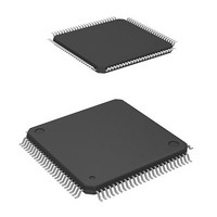
HD64F2239TF20I Renesas Electronics America, HD64F2239TF20I Datasheet - Page 56

HD64F2239TF20I
Manufacturer Part Number
HD64F2239TF20I
Description
MCU 3V 384K I-TEMP 100-TQFP
Manufacturer
Renesas Electronics America
Series
H8® H8S/2200r
Datasheet
1.DF2238RFA6V.pdf
(1048 pages)
Specifications of HD64F2239TF20I
Core Processor
H8S/2000
Core Size
16-Bit
Speed
20MHz
Connectivity
I²C, SCI, SmartCard
Peripherals
DMA, POR, PWM, WDT
Number Of I /o
72
Program Memory Size
384KB (384K x 8)
Program Memory Type
FLASH
Ram Size
32K x 8
Voltage - Supply (vcc/vdd)
2.7 V ~ 3.6 V
Data Converters
A/D 8x10b; D/A 2x8b
Oscillator Type
Internal
Operating Temperature
-40°C ~ 85°C
Package / Case
100-TQFP, 100-VQFP
Lead Free Status / RoHS Status
Contains lead / RoHS non-compliant
Eeprom Size
-
Available stocks
Company
Part Number
Manufacturer
Quantity
Price
Company:
Part Number:
HD64F2239TF20I
Manufacturer:
Renesas Electronics America
Quantity:
10 000
- Current page: 56 of 1048
- Download datasheet (6Mb)
Table 9.7
Section 10 I/O Ports
Table 10.1
Table 10.2
Table 10.3
Table 10.4
Table 10.5
Table 10.6
Table 10.7
Section 11 16-Bit Timer Pulse Unit (TPU)
Table 11.1
Table 11.2
Table 11.3
Table 11.4
Table 11.5
Table 11.6
Table 11.7
Table 11.8
Table 11.9
Table 11.10 TPSC2 to TPSC0 (Channel 5)................................................................................ 371
Table 11.11 MD3 to MD0.......................................................................................................... 373
Table 11.12 TIORH_0................................................................................................................ 375
Table 11.13 TIORL_0 ................................................................................................................ 376
Table 11.14 TIOR_1 .................................................................................................................. 377
Table 11.15 TIOR_2 .................................................................................................................. 378
Table 11.16 TIORH_3................................................................................................................ 379
Table 11.17 TIORL_3 ................................................................................................................ 380
Table 11.18 TIOR_4 .................................................................................................................. 381
Table 11.19 TIOR_5 .................................................................................................................. 382
Table 11.20 TIORH_0................................................................................................................ 383
Table 11.21 TIORL_0 ................................................................................................................ 384
Table 11.22 TIOR_1 .................................................................................................................. 385
Table 11.23 TIOR_2 .................................................................................................................. 386
Table 11.24 TIORH_3................................................................................................................ 387
Table 11.25 TIORL_3 ................................................................................................................ 388
Table 11.26 TIOR_4 .................................................................................................................. 389
Table 11.27 TIOR_5 .................................................................................................................. 390
Table 11.28 Register Combinations in Buffer Operation........................................................... 405
Rev. 6.00 Mar. 18, 2010 Page liv of lx
REJ09B0054-0600
Number of States Required for Each Execution Status .......................................... 300
Port Functions ........................................................................................................ 306
Input Pull-Up MOS States in Port A ...................................................................... 332
Input Pull-Up MOS States in Port B ...................................................................... 339
Input Pull-Up MOS States in Port C ...................................................................... 342
Input Pull-Up MOS States in Port D ...................................................................... 346
Input Pull-Up MOS States in Port E ...................................................................... 349
Examples of Ways to Handle Unused Input Pins................................................... 358
TPU Functions ....................................................................................................... 360
Pin Configuration ................................................................................................... 364
CCLR2 to CCLR0 (Channels 0 and 3)................................................................... 368
CCLR2 to CCLR0 (Channels 1, 2, 4, and 5).......................................................... 368
TPSC2 to TPSC0 (Channel 0)................................................................................ 369
TPSC2 to TPSC0 (Channel 1)................................................................................ 369
TPSC2 to TPSC0 (Channel 2)................................................................................ 370
TPSC2 to TPSC0 (Channel 3)................................................................................ 370
TPSC2 to TPSC0 (Channel 4)................................................................................ 371
Related parts for HD64F2239TF20I
Image
Part Number
Description
Manufacturer
Datasheet
Request
R

Part Number:
Description:
KIT STARTER FOR M16C/29
Manufacturer:
Renesas Electronics America
Datasheet:

Part Number:
Description:
KIT STARTER FOR R8C/2D
Manufacturer:
Renesas Electronics America
Datasheet:

Part Number:
Description:
R0K33062P STARTER KIT
Manufacturer:
Renesas Electronics America
Datasheet:

Part Number:
Description:
KIT STARTER FOR R8C/23 E8A
Manufacturer:
Renesas Electronics America
Datasheet:

Part Number:
Description:
KIT STARTER FOR R8C/25
Manufacturer:
Renesas Electronics America
Datasheet:

Part Number:
Description:
KIT STARTER H8S2456 SHARPE DSPLY
Manufacturer:
Renesas Electronics America
Datasheet:

Part Number:
Description:
KIT STARTER FOR R8C38C
Manufacturer:
Renesas Electronics America
Datasheet:

Part Number:
Description:
KIT STARTER FOR R8C35C
Manufacturer:
Renesas Electronics America
Datasheet:

Part Number:
Description:
KIT STARTER FOR R8CL3AC+LCD APPS
Manufacturer:
Renesas Electronics America
Datasheet:

Part Number:
Description:
KIT STARTER FOR RX610
Manufacturer:
Renesas Electronics America
Datasheet:

Part Number:
Description:
KIT STARTER FOR R32C/118
Manufacturer:
Renesas Electronics America
Datasheet:

Part Number:
Description:
KIT DEV RSK-R8C/26-29
Manufacturer:
Renesas Electronics America
Datasheet:

Part Number:
Description:
KIT STARTER FOR SH7124
Manufacturer:
Renesas Electronics America
Datasheet:

Part Number:
Description:
KIT STARTER FOR H8SX/1622
Manufacturer:
Renesas Electronics America
Datasheet:

Part Number:
Description:
KIT DEV FOR SH7203
Manufacturer:
Renesas Electronics America
Datasheet:


