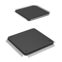
HD64F2239TF20I Renesas Electronics America, HD64F2239TF20I Datasheet - Page 50

HD64F2239TF20I
Manufacturer Part Number
HD64F2239TF20I
Description
MCU 3V 384K I-TEMP 100-TQFP
Manufacturer
Renesas Electronics America
Series
H8® H8S/2200r
Datasheet
1.DF2238RFA6V.pdf
(1048 pages)
Specifications of HD64F2239TF20I
Core Processor
H8S/2000
Core Size
16-Bit
Speed
20MHz
Connectivity
I²C, SCI, SmartCard
Peripherals
DMA, POR, PWM, WDT
Number Of I /o
72
Program Memory Size
384KB (384K x 8)
Program Memory Type
FLASH
Ram Size
32K x 8
Voltage - Supply (vcc/vdd)
2.7 V ~ 3.6 V
Data Converters
A/D 8x10b; D/A 2x8b
Oscillator Type
Internal
Operating Temperature
-40°C ~ 85°C
Package / Case
100-TQFP, 100-VQFP
Lead Free Status / RoHS Status
Contains lead / RoHS non-compliant
Eeprom Size
-
Available stocks
Company
Part Number
Manufacturer
Quantity
Price
Company:
Part Number:
HD64F2239TF20I
Manufacturer:
Renesas Electronics America
Quantity:
10 000
- Current page: 50 of 1048
- Download datasheet (6Mb)
Figure 15.44 Operation when Switching from SCK Pin Function to Port Pin Function
Section 16 I
Figure 16.1
Figure 16.2
Figure 16.3
Figure 16.4
Figure 16.5
Figure 16.6
Figure 16.7
Figure 16.8
Figure 16.9
Figure 16.10 Flowchart for Master Receive Mode (Receiving Multiple Bytes)
Figure 16.11 Flowchart for Master Receive Mode (Receiving 1 Byte) (WAIT = 1)
Figure 16.12 Example of Master Receive Mode Operation Timing
Figure 16.13 Example of Master Receive Mode Stop Condition Generation Timing
Figure 16.14 Flowchart for Slave Transmit Mode (Example)................................................... 665
Figure 16.15 Example of Slave Receive Mode Operation Timing (1) (MLS = ACKB = 0)..... 667
Figure 16.16 Example of Slave Receive Mode Operation Timing (2) (MLS = ACKB = 0)..... 668
Figure 16.17 Sample Flowchart for Slave Transmit Mode ....................................................... 669
Figure 16.18 Example of Slave Transmit Mode Operation Timing (MLS = 0) ........................ 671
Figure 16.19 IRIC Setting Timing and SCL Control ................................................................ 672
Figure 16.20 Block Diagram of Noise Canceler ....................................................................... 674
Figure 16.21 Points for Attention Concerning Reading of Master Receive Data...................... 680
Figure 16.22 Flowchart and Timing of Start Condition Instruction Issuance for
Figure 16.23 Timing of Stop Condition Issuance...................................................................... 682
Figure 16.24 IRIC Flag Clearance in WAIT = 1 Status ............................................................ 682
Figure 16.25 ICDR Read and ICCR Access Timing in Slave Transmit Mode ......................... 683
Figure 16.26 TRS Bit Setting Timing in Slave Mode ............................................................... 684
Figure 16.27 Diagram of Erroneous Operation Wen Arbitration Is Lost .................................. 686
Figure 16.28 IRIC Flag Clearing Timing in Wait Operation..................................................... 687
Rev. 6.00 Mar. 18, 2010 Page xlviii of lx
REJ09B0054-0600
2
C Bus Interface (IIC) (Option)
(Example of Preventing Low-Level Output)........................................................ 631
Block Diagram of I
I
I
I
I
Flowchart for IIC Initialization (Example) .......................................................... 655
Flowchart for Master Transmit Mode (Example) ................................................ 656
Example of Master Transmit Mode Operation Timing (MLS = WAIT = 0) ....... 658
Example of Master Transmit Mode Stop Condition Generation Timing
(MLS = WAIT = 0).............................................................................................. 658
(WAIT = 1) (Example)......................................................................................... 660
(Example)............................................................................................................. 661
(MLS = ACKB = 0, WAIT = 1)........................................................................... 663
(MLS = ACKB = 0, WAIT = 1)........................................................................... 664
Retransmission ..................................................................................................... 681
2
2
2
2
C Bus Interface Connections (Example: This LSI as Master) ........................... 636
C Bus Data Formats (I
C Bus Data Format (Serial Format) ................................................................... 654
C Bus Timing..................................................................................................... 654
2
C Bus Interface..................................................................... 635
2
C Bus Formats) ............................................................. 654
Related parts for HD64F2239TF20I
Image
Part Number
Description
Manufacturer
Datasheet
Request
R

Part Number:
Description:
KIT STARTER FOR M16C/29
Manufacturer:
Renesas Electronics America
Datasheet:

Part Number:
Description:
KIT STARTER FOR R8C/2D
Manufacturer:
Renesas Electronics America
Datasheet:

Part Number:
Description:
R0K33062P STARTER KIT
Manufacturer:
Renesas Electronics America
Datasheet:

Part Number:
Description:
KIT STARTER FOR R8C/23 E8A
Manufacturer:
Renesas Electronics America
Datasheet:

Part Number:
Description:
KIT STARTER FOR R8C/25
Manufacturer:
Renesas Electronics America
Datasheet:

Part Number:
Description:
KIT STARTER H8S2456 SHARPE DSPLY
Manufacturer:
Renesas Electronics America
Datasheet:

Part Number:
Description:
KIT STARTER FOR R8C38C
Manufacturer:
Renesas Electronics America
Datasheet:

Part Number:
Description:
KIT STARTER FOR R8C35C
Manufacturer:
Renesas Electronics America
Datasheet:

Part Number:
Description:
KIT STARTER FOR R8CL3AC+LCD APPS
Manufacturer:
Renesas Electronics America
Datasheet:

Part Number:
Description:
KIT STARTER FOR RX610
Manufacturer:
Renesas Electronics America
Datasheet:

Part Number:
Description:
KIT STARTER FOR R32C/118
Manufacturer:
Renesas Electronics America
Datasheet:

Part Number:
Description:
KIT DEV RSK-R8C/26-29
Manufacturer:
Renesas Electronics America
Datasheet:

Part Number:
Description:
KIT STARTER FOR SH7124
Manufacturer:
Renesas Electronics America
Datasheet:

Part Number:
Description:
KIT STARTER FOR H8SX/1622
Manufacturer:
Renesas Electronics America
Datasheet:

Part Number:
Description:
KIT DEV FOR SH7203
Manufacturer:
Renesas Electronics America
Datasheet:


