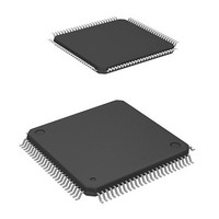
HD64F2239TF20I Renesas Electronics America, HD64F2239TF20I Datasheet - Page 709

HD64F2239TF20I
Manufacturer Part Number
HD64F2239TF20I
Description
MCU 3V 384K I-TEMP 100-TQFP
Manufacturer
Renesas Electronics America
Series
H8® H8S/2200r
Datasheet
1.DF2238RFA6V.pdf
(1048 pages)
Specifications of HD64F2239TF20I
Core Processor
H8S/2000
Core Size
16-Bit
Speed
20MHz
Connectivity
I²C, SCI, SmartCard
Peripherals
DMA, POR, PWM, WDT
Number Of I /o
72
Program Memory Size
384KB (384K x 8)
Program Memory Type
FLASH
Ram Size
32K x 8
Voltage - Supply (vcc/vdd)
2.7 V ~ 3.6 V
Data Converters
A/D 8x10b; D/A 2x8b
Oscillator Type
Internal
Operating Temperature
-40°C ~ 85°C
Package / Case
100-TQFP, 100-VQFP
Lead Free Status / RoHS Status
Contains lead / RoHS non-compliant
Eeprom Size
-
Available stocks
Company
Part Number
Manufacturer
Quantity
Price
Company:
Part Number:
HD64F2239TF20I
Manufacturer:
Renesas Electronics America
Quantity:
10 000
- Current page: 709 of 1048
- Download datasheet (6Mb)
Bit
0
When, with the I
must be checked in order to identify the source that set IRIC to 1. Although each source has a
corresponding flag, caution is needed at the end of a transfer.
When the TDRE or RDRF internal flag is set, the readable IRTR flag may or may not be set. Even
when data transfer is complete, the DTC activation request flag, IRTR, is not set until a
retransmission start condition or stop condition is detected after a slave address (SVA) or general
call address matched in the I
Even when the IRIC flag and IRTR flag are set, the TDRE or RDRF internal flag may not be set.
For a continuous transfer using the DTC, the IRIC or IRTR flag is not cleared at the completion of
the specified number of times of transfers. On the other hand, the TDRE and RDRF flags are
cleared because the specified number of times of read/write operations have been complete.
Table 16.4 shows the relationship between the flags and the transfer states.
Bit Name
SCP
2
C bus format selected, IRIC is set to 1 and an interrupt is generated, other flags
Initial
Value
1
2
C bus format slave mode.
R/W
W
Description
Start Condition/Stop Condition Prohibit bit
The SCP bit controls the issue of start/stop conditions in
master mode.
To issue a start condition, write 1 in BBSY and 0 in SCP. A
retransmit start condition is issued in the same way. To issue
a stop condition, write 0 in BBSY and 0 in SCP. This bit is
always read as 1. If 1 is written, the data is not stored.
Section 16 I
Rev. 6.00 Mar. 18, 2010 Page 647 of 982
2
C Bus Interface (IIC) (Option)
REJ09B0054-0600
Related parts for HD64F2239TF20I
Image
Part Number
Description
Manufacturer
Datasheet
Request
R

Part Number:
Description:
KIT STARTER FOR M16C/29
Manufacturer:
Renesas Electronics America
Datasheet:

Part Number:
Description:
KIT STARTER FOR R8C/2D
Manufacturer:
Renesas Electronics America
Datasheet:

Part Number:
Description:
R0K33062P STARTER KIT
Manufacturer:
Renesas Electronics America
Datasheet:

Part Number:
Description:
KIT STARTER FOR R8C/23 E8A
Manufacturer:
Renesas Electronics America
Datasheet:

Part Number:
Description:
KIT STARTER FOR R8C/25
Manufacturer:
Renesas Electronics America
Datasheet:

Part Number:
Description:
KIT STARTER H8S2456 SHARPE DSPLY
Manufacturer:
Renesas Electronics America
Datasheet:

Part Number:
Description:
KIT STARTER FOR R8C38C
Manufacturer:
Renesas Electronics America
Datasheet:

Part Number:
Description:
KIT STARTER FOR R8C35C
Manufacturer:
Renesas Electronics America
Datasheet:

Part Number:
Description:
KIT STARTER FOR R8CL3AC+LCD APPS
Manufacturer:
Renesas Electronics America
Datasheet:

Part Number:
Description:
KIT STARTER FOR RX610
Manufacturer:
Renesas Electronics America
Datasheet:

Part Number:
Description:
KIT STARTER FOR R32C/118
Manufacturer:
Renesas Electronics America
Datasheet:

Part Number:
Description:
KIT DEV RSK-R8C/26-29
Manufacturer:
Renesas Electronics America
Datasheet:

Part Number:
Description:
KIT STARTER FOR SH7124
Manufacturer:
Renesas Electronics America
Datasheet:

Part Number:
Description:
KIT STARTER FOR H8SX/1622
Manufacturer:
Renesas Electronics America
Datasheet:

Part Number:
Description:
KIT DEV FOR SH7203
Manufacturer:
Renesas Electronics America
Datasheet:


