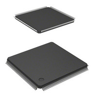
HD6417706F133 Renesas Electronics America, HD6417706F133 Datasheet - Page 35

HD6417706F133
Manufacturer Part Number
HD6417706F133
Description
IC SUPERH MPU ROMLESS 176LQFP
Manufacturer
Renesas Electronics America
Series
SuperH® SH7700r
Datasheet
1.HD6417706F133V.pdf
(751 pages)
Specifications of HD6417706F133
Core Processor
SH-3
Core Size
32-Bit
Speed
133MHz
Connectivity
EBI/EMI, FIFO, SCI, SmartCard
Peripherals
DMA, POR, WDT
Number Of I /o
103
Program Memory Type
ROMless
Ram Size
16K x 8
Voltage - Supply (vcc/vdd)
1.75 V ~ 2.05 V
Oscillator Type
Internal
Operating Temperature
-20°C ~ 75°C
Package / Case
176-LQFP
Lead Free Status / RoHS Status
Contains lead / RoHS non-compliant
Eeprom Size
-
Program Memory Size
-
Data Converters
-
Available stocks
Company
Part Number
Manufacturer
Quantity
Price
Part Number:
HD6417706F133
Manufacturer:
RENESAS/瑞萨
Quantity:
20 000
Company:
Part Number:
HD6417706F133V
Manufacturer:
EDISON
Quantity:
2 000
Company:
Part Number:
HD6417706F133V
Manufacturer:
Renesas Electronics America
Quantity:
10 000
Part Number:
HD6417706F133V
Manufacturer:
RENESAS/瑞萨
Quantity:
20 000
- Current page: 35 of 751
- Download datasheet (5Mb)
Section 20 D/A Converter (DAC)
20.1 Feature .............................................................................................................................. 549
20.2 Input/Output Pin................................................................................................................ 550
20.3 Register Description.......................................................................................................... 550
20.4 Operation .......................................................................................................................... 552
Section 21 User Debugging Interface (H-UDI)
21.1 Feature .............................................................................................................................. 554
21.2 Input/Output Pin................................................................................................................ 554
21.3 Register Description.......................................................................................................... 555
21.4 H-UDI Operations............................................................................................................. 561
21.5 Boundary Scan .................................................................................................................. 564
21.6 Usage Note........................................................................................................................ 565
21.7 Advanced User Debugger (AUD) ..................................................................................... 565
Section 22 Power-Down Modes
22.1 Input/Output Pin................................................................................................................ 569
22.2 Register Description.......................................................................................................... 569
22.3 Operation .......................................................................................................................... 573
20.3.1 D/A Data Registers 0 and 1 (DADR0 and DADR1)............................................ 550
20.3.2 D/A Control Register (DACR) ............................................................................ 550
21.3.1 Bypass Register (SDBPR) ................................................................................... 555
21.3.2 Instruction Register (SDIR) ................................................................................. 555
21.3.3 Boundary Scan Register (SDBSR)....................................................................... 556
21.4.1 TAP Controller .................................................................................................... 561
21.4.2 Reset Configuration ............................................................................................. 562
21.4.3 H-UDI Reset ........................................................................................................ 563
21.4.4 H-UDI Interrupt ................................................................................................... 563
21.4.5 Bypass.................................................................................................................. 563
21.4.6 Using H-UDI to Recover from Sleep Mode ........................................................ 563
21.5.1 Supported Instructions ......................................................................................... 564
21.5.2 Notes for Boundary Scan ..................................................................................... 565
22.2.1 Standby Control Register (STBCR)..................................................................... 569
22.2.2 Standby Control Register 2 (STBCR2)................................................................ 571
22.3.1 Sleep Mode .......................................................................................................... 573
22.3.2 Software Standby Mode....................................................................................... 574
22.3.3 Module Standby Function.................................................................................... 576
22.3.4 Timing of STATUS Pin Changes ........................................................................ 578
22.3.5 Hardware Standby Function ................................................................................ 582
...................................................................................... 567
.................................................................................. 549
Rev. 5.00 May 29, 2006 page xxxiii of xlviii
.......................................................... 553
Related parts for HD6417706F133
Image
Part Number
Description
Manufacturer
Datasheet
Request
R

Part Number:
Description:
KIT STARTER FOR M16C/29
Manufacturer:
Renesas Electronics America
Datasheet:

Part Number:
Description:
KIT STARTER FOR R8C/2D
Manufacturer:
Renesas Electronics America
Datasheet:

Part Number:
Description:
R0K33062P STARTER KIT
Manufacturer:
Renesas Electronics America
Datasheet:

Part Number:
Description:
KIT STARTER FOR R8C/23 E8A
Manufacturer:
Renesas Electronics America
Datasheet:

Part Number:
Description:
KIT STARTER FOR R8C/25
Manufacturer:
Renesas Electronics America
Datasheet:

Part Number:
Description:
KIT STARTER H8S2456 SHARPE DSPLY
Manufacturer:
Renesas Electronics America
Datasheet:

Part Number:
Description:
KIT STARTER FOR R8C38C
Manufacturer:
Renesas Electronics America
Datasheet:

Part Number:
Description:
KIT STARTER FOR R8C35C
Manufacturer:
Renesas Electronics America
Datasheet:

Part Number:
Description:
KIT STARTER FOR R8CL3AC+LCD APPS
Manufacturer:
Renesas Electronics America
Datasheet:

Part Number:
Description:
KIT STARTER FOR RX610
Manufacturer:
Renesas Electronics America
Datasheet:

Part Number:
Description:
KIT STARTER FOR R32C/118
Manufacturer:
Renesas Electronics America
Datasheet:

Part Number:
Description:
KIT DEV RSK-R8C/26-29
Manufacturer:
Renesas Electronics America
Datasheet:

Part Number:
Description:
KIT STARTER FOR SH7124
Manufacturer:
Renesas Electronics America
Datasheet:

Part Number:
Description:
KIT STARTER FOR H8SX/1622
Manufacturer:
Renesas Electronics America
Datasheet:

Part Number:
Description:
KIT DEV FOR SH7203
Manufacturer:
Renesas Electronics America
Datasheet:


