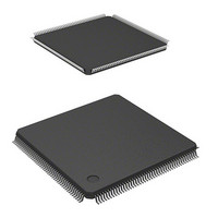
HD6417706F133 Renesas Electronics America, HD6417706F133 Datasheet - Page 626

HD6417706F133
Manufacturer Part Number
HD6417706F133
Description
IC SUPERH MPU ROMLESS 176LQFP
Manufacturer
Renesas Electronics America
Series
SuperH® SH7700r
Datasheet
1.HD6417706F133V.pdf
(751 pages)
Specifications of HD6417706F133
Core Processor
SH-3
Core Size
32-Bit
Speed
133MHz
Connectivity
EBI/EMI, FIFO, SCI, SmartCard
Peripherals
DMA, POR, WDT
Number Of I /o
103
Program Memory Type
ROMless
Ram Size
16K x 8
Voltage - Supply (vcc/vdd)
1.75 V ~ 2.05 V
Oscillator Type
Internal
Operating Temperature
-20°C ~ 75°C
Package / Case
176-LQFP
Lead Free Status / RoHS Status
Contains lead / RoHS non-compliant
Eeprom Size
-
Program Memory Size
-
Data Converters
-
Available stocks
Company
Part Number
Manufacturer
Quantity
Price
Part Number:
HD6417706F133
Manufacturer:
RENESAS/瑞萨
Quantity:
20 000
Company:
Part Number:
HD6417706F133V
Manufacturer:
EDISON
Quantity:
2 000
Company:
Part Number:
HD6417706F133V
Manufacturer:
Renesas Electronics America
Quantity:
10 000
Part Number:
HD6417706F133V
Manufacturer:
RENESAS/瑞萨
Quantity:
20 000
- Current page: 626 of 751
- Download datasheet (5Mb)
Section 22 Power-Down Modes
Clock Pause Function
In software standby mode, the clock input from the EXTAL pin or CKIO pin can be halted and the
frequency can be changed. This function is used as follows:
1. Enter software standby mode using the appropriate procedures.
2. Once software standby mode is entered and the clock stopped within the chip, the STATUS1
3. Once the STATUS1 pin goes low and the STATUS0 pin goes high, the input clock is stopped
4. When the frequency is changed, an NMI, IRL, IRQ or on-chip supporting module (except the
5. After the time set in the WDT has elapsed, the clock starts being applied internally within the
22.3.3
Transition to Module Standby Function
Setting the standby control register MSTP8 to MSTP4, MSTP2 to MSTP0 bits to 1 halts the
supply of clocks to the corresponding on-chip supporting modules. This function can be used to
reduce the power consumption in normal mode and sleep mode. The module standby function
holds the state prior to halt of the external pins of the on-chip supporting modules. TMU external
pins hold their state prior to the halt. SCI external pins go to the reset state. With a few exceptions,
all registers hold their values.
If the realtime clock (RTC) is set to module standby mode (bit 1 in standby control register
(STBCR) set to 1) before any register in the RTC, SCI, or TMU is accessed, registers in the serial
communication interface (SCI) or timer unit (TMU) may not be read properly. To avoid this
problem, access (read or write) any register in the RTC, SCI, or TMU once or more before setting
the RTC to module standby mode.
Rev. 5.00 May 29, 2006 page 576 of 698
REJ09B0146-0500
pin output is low and the STATUS0 pin output is high.
or the frequency is changed.
internal timer) interrupt is input after the change. When the clock is stopped, the same
interrupts are input after the clock is applied.
chip, the STATUS1 and STATUS0 pins both go low, interrupts are handled, and operation
resumes.
Module Standby Function
Related parts for HD6417706F133
Image
Part Number
Description
Manufacturer
Datasheet
Request
R

Part Number:
Description:
KIT STARTER FOR M16C/29
Manufacturer:
Renesas Electronics America
Datasheet:

Part Number:
Description:
KIT STARTER FOR R8C/2D
Manufacturer:
Renesas Electronics America
Datasheet:

Part Number:
Description:
R0K33062P STARTER KIT
Manufacturer:
Renesas Electronics America
Datasheet:

Part Number:
Description:
KIT STARTER FOR R8C/23 E8A
Manufacturer:
Renesas Electronics America
Datasheet:

Part Number:
Description:
KIT STARTER FOR R8C/25
Manufacturer:
Renesas Electronics America
Datasheet:

Part Number:
Description:
KIT STARTER H8S2456 SHARPE DSPLY
Manufacturer:
Renesas Electronics America
Datasheet:

Part Number:
Description:
KIT STARTER FOR R8C38C
Manufacturer:
Renesas Electronics America
Datasheet:

Part Number:
Description:
KIT STARTER FOR R8C35C
Manufacturer:
Renesas Electronics America
Datasheet:

Part Number:
Description:
KIT STARTER FOR R8CL3AC+LCD APPS
Manufacturer:
Renesas Electronics America
Datasheet:

Part Number:
Description:
KIT STARTER FOR RX610
Manufacturer:
Renesas Electronics America
Datasheet:

Part Number:
Description:
KIT STARTER FOR R32C/118
Manufacturer:
Renesas Electronics America
Datasheet:

Part Number:
Description:
KIT DEV RSK-R8C/26-29
Manufacturer:
Renesas Electronics America
Datasheet:

Part Number:
Description:
KIT STARTER FOR SH7124
Manufacturer:
Renesas Electronics America
Datasheet:

Part Number:
Description:
KIT STARTER FOR H8SX/1622
Manufacturer:
Renesas Electronics America
Datasheet:

Part Number:
Description:
KIT DEV FOR SH7203
Manufacturer:
Renesas Electronics America
Datasheet:


