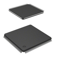
HD6417706F133 Renesas Electronics America, HD6417706F133 Datasheet - Page 661

HD6417706F133
Manufacturer Part Number
HD6417706F133
Description
IC SUPERH MPU ROMLESS 176LQFP
Manufacturer
Renesas Electronics America
Series
SuperH® SH7700r
Datasheet
1.HD6417706F133V.pdf
(751 pages)
Specifications of HD6417706F133
Core Processor
SH-3
Core Size
32-Bit
Speed
133MHz
Connectivity
EBI/EMI, FIFO, SCI, SmartCard
Peripherals
DMA, POR, WDT
Number Of I /o
103
Program Memory Type
ROMless
Ram Size
16K x 8
Voltage - Supply (vcc/vdd)
1.75 V ~ 2.05 V
Oscillator Type
Internal
Operating Temperature
-20°C ~ 75°C
Package / Case
176-LQFP
Lead Free Status / RoHS Status
Contains lead / RoHS non-compliant
Eeprom Size
-
Program Memory Size
-
Data Converters
-
Available stocks
Company
Part Number
Manufacturer
Quantity
Price
Part Number:
HD6417706F133
Manufacturer:
RENESAS/瑞萨
Quantity:
20 000
Company:
Part Number:
HD6417706F133V
Manufacturer:
EDISON
Quantity:
2 000
Company:
Part Number:
HD6417706F133V
Manufacturer:
Renesas Electronics America
Quantity:
10 000
Part Number:
HD6417706F133V
Manufacturer:
RENESAS/瑞萨
Quantity:
20 000
- Current page: 661 of 751
- Download datasheet (5Mb)
Notes: Regardless of whether PLL or RTC is used, connect Vcc – PLL and Vcc – RTC to Vcc, and
Table 24.3 Permitted Output Current Values
Conditions: VccQ = 3.3 ± 0.3 V, Vcc = 1.9 ± 0.15 V, AVcc = 3.3 ± 0.3 V, Ta = –20 to +75°C
Caution: To ensure LSI reliability, do not exceed the value for output current given in Table 24.3.
Item
Analog
power-
supply
current
Item
Output low-level permissible current (per pin)
Output low-level permissible current (total)
Output high-level permissible current (per pin)
Output high-level permissible current (total)
Vss – PLL and Vss – RTC to Vss.
AVcc must be under condition of VccQ – 0.3 V
converters are not used, do not leave the AVcc and AVss pins open. Connect AVcc to
VccQ, and connect AVss to VssQ.
Current dissipation values shown are the values at which all output pins are without load
under conditions of V
1. No external bus cycles except refresh cycles.
2. Total current of Vcc, Vcc – PLL1, and Vcc – PLL2
3. Current of VccQ
4. Current of Vcc – RTC
5. Only in software standby mode
During A/D
conversion
During A/D
and D/A
conversion
Idle
Symbol
AIcc
IH
min = VccQ – 0.5 V, V
Min
—
—
—
Typ
0.8
2.4
0.01
IL
max = 0.5 V.
Symbol
I
∑ I
–I
∑ (–I
OL
OH
Max
2
6
5.0
OL
AVcc
Rev. 5.00 May 29, 2006 page 611 of 698
OH
)
Section 24 Electrical Characteristics
VccQ + 0.3 V. If the A/D and D/A
Unit Measurement Conditions
mA
mA
µA
Min
—
—
—
—
Ta = 25°C
Typ
—
—
—
—
REJ09B0146-0500
Max
2.0
120
2.0
40
Unit
mA
mA
mA
mA
Related parts for HD6417706F133
Image
Part Number
Description
Manufacturer
Datasheet
Request
R

Part Number:
Description:
KIT STARTER FOR M16C/29
Manufacturer:
Renesas Electronics America
Datasheet:

Part Number:
Description:
KIT STARTER FOR R8C/2D
Manufacturer:
Renesas Electronics America
Datasheet:

Part Number:
Description:
R0K33062P STARTER KIT
Manufacturer:
Renesas Electronics America
Datasheet:

Part Number:
Description:
KIT STARTER FOR R8C/23 E8A
Manufacturer:
Renesas Electronics America
Datasheet:

Part Number:
Description:
KIT STARTER FOR R8C/25
Manufacturer:
Renesas Electronics America
Datasheet:

Part Number:
Description:
KIT STARTER H8S2456 SHARPE DSPLY
Manufacturer:
Renesas Electronics America
Datasheet:

Part Number:
Description:
KIT STARTER FOR R8C38C
Manufacturer:
Renesas Electronics America
Datasheet:

Part Number:
Description:
KIT STARTER FOR R8C35C
Manufacturer:
Renesas Electronics America
Datasheet:

Part Number:
Description:
KIT STARTER FOR R8CL3AC+LCD APPS
Manufacturer:
Renesas Electronics America
Datasheet:

Part Number:
Description:
KIT STARTER FOR RX610
Manufacturer:
Renesas Electronics America
Datasheet:

Part Number:
Description:
KIT STARTER FOR R32C/118
Manufacturer:
Renesas Electronics America
Datasheet:

Part Number:
Description:
KIT DEV RSK-R8C/26-29
Manufacturer:
Renesas Electronics America
Datasheet:

Part Number:
Description:
KIT STARTER FOR SH7124
Manufacturer:
Renesas Electronics America
Datasheet:

Part Number:
Description:
KIT STARTER FOR H8SX/1622
Manufacturer:
Renesas Electronics America
Datasheet:

Part Number:
Description:
KIT DEV FOR SH7203
Manufacturer:
Renesas Electronics America
Datasheet:


