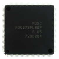
M3087BFLBGP#U5 Renesas Electronics America, M3087BFLBGP#U5 Datasheet - Page 13

M3087BFLBGP#U5
Manufacturer Part Number
M3087BFLBGP#U5
Description
IC M32C/87 MCU FLASH 144LQFP
Manufacturer
Renesas Electronics America
Series
M16C™ M32C/80r
Datasheet
1.M3087BFLGPU3.pdf
(629 pages)
Specifications of M3087BFLBGP#U5
Core Processor
M32C/80
Core Size
16/32-Bit
Speed
32MHz
Connectivity
EBI/EMI, I²C, IEBus, IrDA, SIO, UART/USART
Peripherals
DMA, POR, PWM, WDT
Number Of I /o
121
Program Memory Size
1MB (1M x 8)
Program Memory Type
FLASH
Ram Size
48K x 8
Voltage - Supply (vcc/vdd)
3 V ~ 5.5 V
Data Converters
A/D 34x10b, D/A 2x8b
Oscillator Type
Internal
Operating Temperature
-20°C ~ 85°C
Package / Case
144-LQFP
For Use With
R0K330879S001BE - KIT DEV RSK M32C/87R0K330879S000BE - KIT DEV RSK M32C/87
Lead Free Status / RoHS Status
Lead free / RoHS Compliant
Eeprom Size
-
Available stocks
Company
Part Number
Manufacturer
Quantity
Price
Part Number:
M3087BFLBGP#U5M3087BFLBGP#U3
Manufacturer:
Renesas Electronics America
Quantity:
10 000
- Current page: 13 of 629
- Download datasheet (16Mb)
15.
16.
17.
18.
14.7
15.1
15.2
16.1
16.2
16.3
17.1
17.2
18.1
18.2
15.1.1
15.1.2
15.1.3
15.1.4
15.2.1
15.2.2
15.2.3
16.3.1
16.3.2
16.3.3
17.1.1
17.1.2
17.1.3
17.1.4
17.1.5
17.1.6
17.1.7
17.2.1
17.2.2
18.1.1
18.1.2
18.1.3
18.1.4
18.1.5
18.1.6
18.1.7
18.2.1
18.2.2
18.2.3
18.2.4
18.2.5
Timers ......................................................................................................................................... 159
Three-Phase Motor Control Timer Function ............................................................................... 196
Serial Interfaces .......................................................................................................................... 214
A/D Converter ............................................................................................................................. 293
Execution Time ..................................................................................................................................... 158
Timer A ................................................................................................................................................. 161
Timer B ................................................................................................................................................. 184
Triangular Wave Modulation Mode ...................................................................................................... 207
Sawtooth Wave Modulation Mode ....................................................................................................... 211
Short Circuit Prevention Features ......................................................................................................... 213
UART0 to UART4 ................................................................................................................................ 215
UART5 and UART6 ............................................................................................................................. 272
Mode Descriptions ................................................................................................................................ 300
Functions ............................................................................................................................................... 309
Timer Mode ...................................................................................................................................... 173
Event Counter Mode ......................................................................................................................... 174
One-Shot Timer Mode ...................................................................................................................... 179
Pulse Width Modulation Mode ......................................................................................................... 181
Timer Mode ...................................................................................................................................... 191
Event Counter Mode ......................................................................................................................... 192
Pulse Period Measurement Mode, Pulse Width Measurement Mode .............................................. 193
Prevention Against Upper/Lower Arm Short Circuit by Program Errors ........................................ 213
Arm Short Circuit Prevention Using Dead Time Timer ................................................................... 213
Forced-Cutoff Function by the NMI Input ....................................................................................... 213
Clock Synchronous Mode ................................................................................................................ 225
Clock Asynchronous (UART) Mode ................................................................................................ 234
Special Mode 1 (I2C Mode) ............................................................................................................. 242
Special Mode 2 ................................................................................................................................. 254
Special Mode 3 (GCI Mode) ............................................................................................................ 259
Special Mode 4 (SIM Mode) ............................................................................................................ 263
Special Mode 5 (IrDA mode) • • • UART0 ...................................................................................... 269
Clock Synchronous Mode ................................................................................................................ 278
Clock Asynchronous (UART) Mode ................................................................................................ 286
One-Shot Mode ................................................................................................................................. 301
Repeat Mode ..................................................................................................................................... 302
Single Sweep Mode .......................................................................................................................... 303
Repeat Sweep Mode 0 ...................................................................................................................... 304
Repeat Sweep Mode 1 ...................................................................................................................... 305
Multi-Port Single Sweep Mode ........................................................................................................ 307
Multi-Port Repeat Sweep Mode 0 .................................................................................................... 308
Resolution ......................................................................................................................................... 309
Sample and Hold .............................................................................................................................. 309
Trigger Select Function .................................................................................................................... 309
DMAC Operating Mode ................................................................................................................... 309
Extended Analog Input Pins ............................................................................................................. 309
A - 4
Related parts for M3087BFLBGP#U5
Image
Part Number
Description
Manufacturer
Datasheet
Request
R

Part Number:
Description:
KIT STARTER FOR M16C/29
Manufacturer:
Renesas Electronics America
Datasheet:

Part Number:
Description:
KIT STARTER FOR R8C/2D
Manufacturer:
Renesas Electronics America
Datasheet:

Part Number:
Description:
R0K33062P STARTER KIT
Manufacturer:
Renesas Electronics America
Datasheet:

Part Number:
Description:
KIT STARTER FOR R8C/23 E8A
Manufacturer:
Renesas Electronics America
Datasheet:

Part Number:
Description:
KIT STARTER FOR R8C/25
Manufacturer:
Renesas Electronics America
Datasheet:

Part Number:
Description:
KIT STARTER H8S2456 SHARPE DSPLY
Manufacturer:
Renesas Electronics America
Datasheet:

Part Number:
Description:
KIT STARTER FOR R8C38C
Manufacturer:
Renesas Electronics America
Datasheet:

Part Number:
Description:
KIT STARTER FOR R8C35C
Manufacturer:
Renesas Electronics America
Datasheet:

Part Number:
Description:
KIT STARTER FOR R8CL3AC+LCD APPS
Manufacturer:
Renesas Electronics America
Datasheet:

Part Number:
Description:
KIT STARTER FOR RX610
Manufacturer:
Renesas Electronics America
Datasheet:

Part Number:
Description:
KIT STARTER FOR R32C/118
Manufacturer:
Renesas Electronics America
Datasheet:

Part Number:
Description:
KIT DEV RSK-R8C/26-29
Manufacturer:
Renesas Electronics America
Datasheet:

Part Number:
Description:
KIT STARTER FOR SH7124
Manufacturer:
Renesas Electronics America
Datasheet:

Part Number:
Description:
KIT STARTER FOR H8SX/1622
Manufacturer:
Renesas Electronics America
Datasheet:

Part Number:
Description:
KIT DEV FOR SH7203
Manufacturer:
Renesas Electronics America
Datasheet:


