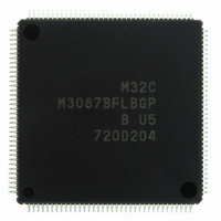
M3087BFLBGP#U5 Renesas Electronics America, M3087BFLBGP#U5 Datasheet - Page 163

M3087BFLBGP#U5
Manufacturer Part Number
M3087BFLBGP#U5
Description
IC M32C/87 MCU FLASH 144LQFP
Manufacturer
Renesas Electronics America
Series
M16C™ M32C/80r
Datasheet
1.M3087BFLGPU3.pdf
(629 pages)
Specifications of M3087BFLBGP#U5
Core Processor
M32C/80
Core Size
16/32-Bit
Speed
32MHz
Connectivity
EBI/EMI, I²C, IEBus, IrDA, SIO, UART/USART
Peripherals
DMA, POR, PWM, WDT
Number Of I /o
121
Program Memory Size
1MB (1M x 8)
Program Memory Type
FLASH
Ram Size
48K x 8
Voltage - Supply (vcc/vdd)
3 V ~ 5.5 V
Data Converters
A/D 34x10b, D/A 2x8b
Oscillator Type
Internal
Operating Temperature
-20°C ~ 85°C
Package / Case
144-LQFP
For Use With
R0K330879S001BE - KIT DEV RSK M32C/87R0K330879S000BE - KIT DEV RSK M32C/87
Lead Free Status / RoHS Status
Lead free / RoHS Compliant
Eeprom Size
-
Available stocks
Company
Part Number
Manufacturer
Quantity
Price
Part Number:
M3087BFLBGP#U5M3087BFLBGP#U3
Manufacturer:
Renesas Electronics America
Quantity:
10 000
- Current page: 163 of 629
- Download datasheet (16Mb)
M32C/87 Group (M32C/87, M32C/87A, M32C/87B)
REJ09B0180-0151 Rev.1.51 Jul 31, 2008
Page 139 of 587
A software trigger or an interrupt request generated by individual peripheral functions can be the DMA transfer request
source. Bits DSEL 4 to DSEL0 in the DMiSL register determine which source is selected. When a software trigger is
selected, a DMA transfer is started by setting the DSR bit in the DMiSL register to 1. When a peripheral function
interrupt request is selected, a DMA transfer is started by an interrupt request generation. The DMA transfer is
performed even if interrupts are disabled by the I flag, IPL, or Interrupt Control Register, since DMAC is free from
these affects. When an interrupt request (DMA request) is generated, the IR bit in the Interrupt Control Register
becomes 1. The IR bit, however, does not become 0 even if the DMA transfer is performed.
Table 13.1
NOTE:
Number of Channels
Transfer memory space
Maximum bytes transferred
DMA request source
Channel priority
Transfer unit
Transfer address
Transfer
mode
DMA interrupt request
generation timing
DMA start
DMA stop
Reload timing to registers DCTi
and DMAi
DMA transfer time
1. Only CAN00, CAN01, and CAN02 interrupt requests can be used for M32C/87A. Any CAN interrupt request
cannot be used for M32C/87B.
Item
Single transfer
Repeat transfer
Single transfer
Repeat transfer
Single transfer
Repeat transfer
DMAC Specifications
4 channels (cycle-steal method)
• From a given address in a 16-Mbyte space to a fixed address in a 16-Mbyte space
• From a fixed address in a 16-Mbyte space to a given address in a 16-Mbyte space
128 Kbytes (when a 16-bit data is transferred)
64 Kbytes (when an 8-bit data is transferred)
• Falling edge or both edges of signals applied to pins INT0 to INT3
• INT6 to INT8 interrupt requests
• Timer A0 to A4 interrupt requests
• Timer B0 to B5 interrupt requests
• UART0 to UART6 transmit/receive interrupt requests
• A/D0 interrupt request
• Intelligent I/O interrupt request
• CAN interrupt request
• Software trigger
DMA0 > DMA1 > DMA2 > DMA3 (DMA0 has the highest priority)
8 bits, 16 bits
Fixed address: one specified address
Incremented address: address which is incremented by a transfer unit on each
successive access.
(Source address and destination address cannot be both fixed nor both
incremented.)
Transfer is completed when the DCTi register (i = 0 to 3) becomes 0000h
When the DCTi register becomes 0000h, values of the DRCi register are reloaded
into the DCTi register and the DMA transfer continues.
When the DCTi register becomes from 0001h to 0000h, a DMA interrupt request is
generated.
DMAC starts a data transfer when a DMA request is generated after bits MDi1 and
MDi0 in the DMDj register (j = 0 to 1) are set to 01b (single transfer), while the DCTi
register is set to 0001h or higher value.
DMAC starts a data transfer when a DMA request is generated after bits MDi1 and
MDi0 are set to 11b (repeat transfer), while the DCTi register is set to 0001h or higher
value.
• When bits MDi1 and MDi0 are set to 00b (DMA disabled)
• When the DCTi register becomes 0000h (no DMA transfer) at completion of DMA
• When bits MDi1 and MDi0 are set to 00b (DMA disabled)
• When the DCTi register becomes 0000h (no DMA transfer) at completion of DMA
Values are reloaded when the DCTi register becomes from 0001h to 0000h in repeat
transfer mode.
Between SFR area and internal RAM transfer: minimum 3 bus clock cycles
transfer, or is set to 0000h by a program.
transfer, or is set to 0000h by a program while the DRCi register is 0000h.
(1)
Specification
13. DMAC
Related parts for M3087BFLBGP#U5
Image
Part Number
Description
Manufacturer
Datasheet
Request
R

Part Number:
Description:
KIT STARTER FOR M16C/29
Manufacturer:
Renesas Electronics America
Datasheet:

Part Number:
Description:
KIT STARTER FOR R8C/2D
Manufacturer:
Renesas Electronics America
Datasheet:

Part Number:
Description:
R0K33062P STARTER KIT
Manufacturer:
Renesas Electronics America
Datasheet:

Part Number:
Description:
KIT STARTER FOR R8C/23 E8A
Manufacturer:
Renesas Electronics America
Datasheet:

Part Number:
Description:
KIT STARTER FOR R8C/25
Manufacturer:
Renesas Electronics America
Datasheet:

Part Number:
Description:
KIT STARTER H8S2456 SHARPE DSPLY
Manufacturer:
Renesas Electronics America
Datasheet:

Part Number:
Description:
KIT STARTER FOR R8C38C
Manufacturer:
Renesas Electronics America
Datasheet:

Part Number:
Description:
KIT STARTER FOR R8C35C
Manufacturer:
Renesas Electronics America
Datasheet:

Part Number:
Description:
KIT STARTER FOR R8CL3AC+LCD APPS
Manufacturer:
Renesas Electronics America
Datasheet:

Part Number:
Description:
KIT STARTER FOR RX610
Manufacturer:
Renesas Electronics America
Datasheet:

Part Number:
Description:
KIT STARTER FOR R32C/118
Manufacturer:
Renesas Electronics America
Datasheet:

Part Number:
Description:
KIT DEV RSK-R8C/26-29
Manufacturer:
Renesas Electronics America
Datasheet:

Part Number:
Description:
KIT STARTER FOR SH7124
Manufacturer:
Renesas Electronics America
Datasheet:

Part Number:
Description:
KIT STARTER FOR H8SX/1622
Manufacturer:
Renesas Electronics America
Datasheet:

Part Number:
Description:
KIT DEV FOR SH7203
Manufacturer:
Renesas Electronics America
Datasheet:


