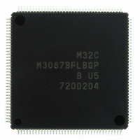
M3087BFLBGP#U5 Renesas Electronics America, M3087BFLBGP#U5 Datasheet - Page 621

M3087BFLBGP#U5
Manufacturer Part Number
M3087BFLBGP#U5
Description
IC M32C/87 MCU FLASH 144LQFP
Manufacturer
Renesas Electronics America
Series
M16C™ M32C/80r
Datasheet
1.M3087BFLGPU3.pdf
(629 pages)
Specifications of M3087BFLBGP#U5
Core Processor
M32C/80
Core Size
16/32-Bit
Speed
32MHz
Connectivity
EBI/EMI, I²C, IEBus, IrDA, SIO, UART/USART
Peripherals
DMA, POR, PWM, WDT
Number Of I /o
121
Program Memory Size
1MB (1M x 8)
Program Memory Type
FLASH
Ram Size
48K x 8
Voltage - Supply (vcc/vdd)
3 V ~ 5.5 V
Data Converters
A/D 34x10b, D/A 2x8b
Oscillator Type
Internal
Operating Temperature
-20°C ~ 85°C
Package / Case
144-LQFP
For Use With
R0K330879S001BE - KIT DEV RSK M32C/87R0K330879S000BE - KIT DEV RSK M32C/87
Lead Free Status / RoHS Status
Lead free / RoHS Compliant
Eeprom Size
-
Available stocks
Company
Part Number
Manufacturer
Quantity
Price
Part Number:
M3087BFLBGP#U5M3087BFLBGP#U3
Manufacturer:
Renesas Electronics America
Quantity:
10 000
- Current page: 621 of 629
- Download datasheet (16Mb)
Rev.
REVISION HISTORY
Date
142-145
146-147
151-158
157-158
159-195
162-171
174-178
182-183
194-195
196-213
198-206
Page
149
150
151
152
172
189
198
-
-
DMAC
• Figures 13.3 to 13.6 Order of register figures rearranged, NOTE partially
• Figures 13.7 and 13.8 Two flow charts added
• Figure Transfer Cycle Examples with the Source-Read Bus Cycle
• Table 13.3 Title and structure partially modified
• Figure 13.9 Title and figure modified
DMACII
• [Term changed]
• Text partially modified
• Table 14.1 Structure and text partially modified
• Figure 14.1 NOTE partially modified
• Figures 14.4 and 14.5 partially modified
Timers
• [Modification throughout all modes]
• Text partially modified, order of register figures rearranged
• Figures 15.4 to 15.13 Register name, bit name, description in Function
• Tables 15.1 and 15.2 Structure partially modified, NOTE 1 added, NOTE
• 15.1.2 Event Counter Mode Structure and text modified
• Figure Counter Reset Timing deleted
• Figures 15.19 and 15.20 Titles and figures partially modified
• Figure 15.26 Register name and bit name partially modified
• Figures 15.29 and 15.30 Titles and figures partially modified
Three-Phase Motor Control Timer Function (fully revised)
• [Term changed]
• Structure, text, tables, and figures modified or added
• Order of register figures rearranged,
• Bits INV01 and INV00 in Figure 16.2 INVC0 Register
• Figure 16.7 Two cases of “when n > 1” and “when n = 1” added under
Serial Interfaces (revised overall)
• Chapter is divided into two sections 17.1 UART 0 to 4 and 17.2 UART 5,6
• Continuous receive mode is deleted in special mode 2
• IEBus mode is deleted, “special mode 4 (IE mode)” is now “special mode
relocatable address → incremented address
Specification tables: Structure, text, and NOTES partially modified
Operation timing diagrams: added or partially modified
Register figures: Register figures of TA0MR to TA4MR in each mode are
moved to earlier in the 15.1 Timer A section.
Positive and negative phases concurrent active → Upper and lower arm
simultaneous turn-on
modified
deleted
Figures 16.2 to 16.10 Register name, bit name, description in Function
Bit name, Function changed
“When bits INV01 and INV00 are set to 11b...”.
4 (SIM mode)”, “special mode 5 (SIM mode)” is now “special mode 5 (IrDA
mode)”, and “special mode 6 (IrDA mode)” is now “special mode 6 (IE
mode)”.
field, and NOTE partially modified
2 moved from NOTE 1
field, and NOTE partially modified
M32C/87 Group Hardware Manual
C - 10
Description
Summary
Related parts for M3087BFLBGP#U5
Image
Part Number
Description
Manufacturer
Datasheet
Request
R

Part Number:
Description:
KIT STARTER FOR M16C/29
Manufacturer:
Renesas Electronics America
Datasheet:

Part Number:
Description:
KIT STARTER FOR R8C/2D
Manufacturer:
Renesas Electronics America
Datasheet:

Part Number:
Description:
R0K33062P STARTER KIT
Manufacturer:
Renesas Electronics America
Datasheet:

Part Number:
Description:
KIT STARTER FOR R8C/23 E8A
Manufacturer:
Renesas Electronics America
Datasheet:

Part Number:
Description:
KIT STARTER FOR R8C/25
Manufacturer:
Renesas Electronics America
Datasheet:

Part Number:
Description:
KIT STARTER H8S2456 SHARPE DSPLY
Manufacturer:
Renesas Electronics America
Datasheet:

Part Number:
Description:
KIT STARTER FOR R8C38C
Manufacturer:
Renesas Electronics America
Datasheet:

Part Number:
Description:
KIT STARTER FOR R8C35C
Manufacturer:
Renesas Electronics America
Datasheet:

Part Number:
Description:
KIT STARTER FOR R8CL3AC+LCD APPS
Manufacturer:
Renesas Electronics America
Datasheet:

Part Number:
Description:
KIT STARTER FOR RX610
Manufacturer:
Renesas Electronics America
Datasheet:

Part Number:
Description:
KIT STARTER FOR R32C/118
Manufacturer:
Renesas Electronics America
Datasheet:

Part Number:
Description:
KIT DEV RSK-R8C/26-29
Manufacturer:
Renesas Electronics America
Datasheet:

Part Number:
Description:
KIT STARTER FOR SH7124
Manufacturer:
Renesas Electronics America
Datasheet:

Part Number:
Description:
KIT STARTER FOR H8SX/1622
Manufacturer:
Renesas Electronics America
Datasheet:

Part Number:
Description:
KIT DEV FOR SH7203
Manufacturer:
Renesas Electronics America
Datasheet:


