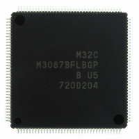
M3087BFLBGP#U5 Renesas Electronics America, M3087BFLBGP#U5 Datasheet - Page 75

M3087BFLBGP#U5
Manufacturer Part Number
M3087BFLBGP#U5
Description
IC M32C/87 MCU FLASH 144LQFP
Manufacturer
Renesas Electronics America
Series
M16C™ M32C/80r
Datasheet
1.M3087BFLGPU3.pdf
(629 pages)
Specifications of M3087BFLBGP#U5
Core Processor
M32C/80
Core Size
16/32-Bit
Speed
32MHz
Connectivity
EBI/EMI, I²C, IEBus, IrDA, SIO, UART/USART
Peripherals
DMA, POR, PWM, WDT
Number Of I /o
121
Program Memory Size
1MB (1M x 8)
Program Memory Type
FLASH
Ram Size
48K x 8
Voltage - Supply (vcc/vdd)
3 V ~ 5.5 V
Data Converters
A/D 34x10b, D/A 2x8b
Oscillator Type
Internal
Operating Temperature
-20°C ~ 85°C
Package / Case
144-LQFP
For Use With
R0K330879S001BE - KIT DEV RSK M32C/87R0K330879S000BE - KIT DEV RSK M32C/87
Lead Free Status / RoHS Status
Lead free / RoHS Compliant
Eeprom Size
-
Available stocks
Company
Part Number
Manufacturer
Quantity
Price
Part Number:
M3087BFLBGP#U5M3087BFLBGP#U3
Manufacturer:
Renesas Electronics America
Quantity:
10 000
- Current page: 75 of 629
- Download datasheet (16Mb)
M32C/87 Group (M32C/87, M32C/87A, M32C/87B)
REJ09B0180-0151 Rev.1.51 Jul 31, 2008
Page 51 of 587
6.
The power supply voltage detection function has the Vdet3 detection function, Vdet4 detection function, and cold
start/warm start determination function. The Vdet3 detection function and Vdet4 detection function detect the changes
in voltage and trigger the events. The cold start/warm start determination function determines whether the MCU is
reset at power-on or reset while running.
The power supply voltage detection function is available only with VCC1 = 4.2V to 5.5V standard.
Figure 6.1 shows a block diagram of the voltage detection circuit. Figures 6.2 to 6.4 show registers associated with the
voltage detection function.
Figure 6.1
CPU clock
Power Supply Voltage Detection Function
VCC1
CM10: bit in the CM1 register
VC13: bit in the VCR1 register
VC26, VC27: bits in the VCR2 register
DF1 and DF0, D40, D41, D42: bits in the D4INT register
WDC5: bit in the WDC register
NOTE:
1. When the VC27 bit in the VCR2 register is set to 0 (Vdet4 detection function not used), the Vdet4 detection signal becomes “H”.
Power Supply Voltage Detection Function Block Diagram
Vdet3 detection function
Vdet4 detection function
Cold start/warm start determination function
WAIT instruction (wait mode)
VC27
CM10
Write a given value to
VC26
+
the WDC register
Hardware reset 1
1/8
E
at power-on
≥Vdet3
CM10
1/2
Vdet4 detection signal
Digital filter
1/2
+
E
≥Vdet3
(rejection range: 200 ns)
1/2
Analog Filter
D41
(1)
00b
01b
10b
11b
R
S
D42 bit
WDC5
Latch
DF1 to DF0
Q
VC13
Output one-shot pulse when the
D42 bit becomes 0 to 1.
1 shot
T
COLD/WARM
(Cold start, warm start)
D40
Q
6. Power Supply Voltage Detection Function
Wait time to release hardware reset 2:
td(S-R)
Watchdog timer
Oscillation stop
detection
interrupt signal
Vdet4 detection
interrupt signal
interrupt signal
Internal reset signal
(active “L”)
Watchdog timer
interrupt request
Related parts for M3087BFLBGP#U5
Image
Part Number
Description
Manufacturer
Datasheet
Request
R

Part Number:
Description:
KIT STARTER FOR M16C/29
Manufacturer:
Renesas Electronics America
Datasheet:

Part Number:
Description:
KIT STARTER FOR R8C/2D
Manufacturer:
Renesas Electronics America
Datasheet:

Part Number:
Description:
R0K33062P STARTER KIT
Manufacturer:
Renesas Electronics America
Datasheet:

Part Number:
Description:
KIT STARTER FOR R8C/23 E8A
Manufacturer:
Renesas Electronics America
Datasheet:

Part Number:
Description:
KIT STARTER FOR R8C/25
Manufacturer:
Renesas Electronics America
Datasheet:

Part Number:
Description:
KIT STARTER H8S2456 SHARPE DSPLY
Manufacturer:
Renesas Electronics America
Datasheet:

Part Number:
Description:
KIT STARTER FOR R8C38C
Manufacturer:
Renesas Electronics America
Datasheet:

Part Number:
Description:
KIT STARTER FOR R8C35C
Manufacturer:
Renesas Electronics America
Datasheet:

Part Number:
Description:
KIT STARTER FOR R8CL3AC+LCD APPS
Manufacturer:
Renesas Electronics America
Datasheet:

Part Number:
Description:
KIT STARTER FOR RX610
Manufacturer:
Renesas Electronics America
Datasheet:

Part Number:
Description:
KIT STARTER FOR R32C/118
Manufacturer:
Renesas Electronics America
Datasheet:

Part Number:
Description:
KIT DEV RSK-R8C/26-29
Manufacturer:
Renesas Electronics America
Datasheet:

Part Number:
Description:
KIT STARTER FOR SH7124
Manufacturer:
Renesas Electronics America
Datasheet:

Part Number:
Description:
KIT STARTER FOR H8SX/1622
Manufacturer:
Renesas Electronics America
Datasheet:

Part Number:
Description:
KIT DEV FOR SH7203
Manufacturer:
Renesas Electronics America
Datasheet:


