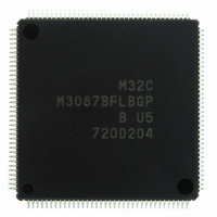
M3087BFLBGP#U5 Renesas Electronics America, M3087BFLBGP#U5 Datasheet - Page 620

M3087BFLBGP#U5
Manufacturer Part Number
M3087BFLBGP#U5
Description
IC M32C/87 MCU FLASH 144LQFP
Manufacturer
Renesas Electronics America
Series
M16C™ M32C/80r
Datasheet
1.M3087BFLGPU3.pdf
(629 pages)
Specifications of M3087BFLBGP#U5
Core Processor
M32C/80
Core Size
16/32-Bit
Speed
32MHz
Connectivity
EBI/EMI, I²C, IEBus, IrDA, SIO, UART/USART
Peripherals
DMA, POR, PWM, WDT
Number Of I /o
121
Program Memory Size
1MB (1M x 8)
Program Memory Type
FLASH
Ram Size
48K x 8
Voltage - Supply (vcc/vdd)
3 V ~ 5.5 V
Data Converters
A/D 34x10b, D/A 2x8b
Oscillator Type
Internal
Operating Temperature
-20°C ~ 85°C
Package / Case
144-LQFP
For Use With
R0K330879S001BE - KIT DEV RSK M32C/87R0K330879S000BE - KIT DEV RSK M32C/87
Lead Free Status / RoHS Status
Lead free / RoHS Compliant
Eeprom Size
-
Available stocks
Company
Part Number
Manufacturer
Quantity
Price
Part Number:
M3087BFLBGP#U5M3087BFLBGP#U3
Manufacturer:
Renesas Electronics America
Quantity:
10 000
- Current page: 620 of 629
- Download datasheet (16Mb)
Rev.
REVISION HISTORY
Date
101-102
106-127
123-124
129-130
131-133
134-137
138-150
Page
101
104
105
109
111
112
116
118
119
120
126
128
134
135
136
139
141
92
93
95
96
97
97
98
99
−
-
Clock Generation Circuits
• Figure 9.11 Flow chart partially modified
• Table 9.3 Structure partially modified, Figure 9.12 Flow chart partially
• Table 9.4 Structure partially modified, Table 9.5 Bit setting value partially
• Figure 9.13 added (entering wait mode from Low-power consumption
• “High-speed mode” and “Medium-speed mode” are changed to “Main
• 9.5.1.7 Main Clock Direct Mode added
• Table CPU Clock Source and Bit Settings Structure modified became
• 9.5.2.2 Entering Wait Mode Procedure became the flow chart
• Table 9.8 CAN interrupts usage conditions revised
• 9.5.3.1 Entering Stop Mode The program example added, procedures
• Figure Status Transition in Wait Mode and Stop Mode deleted
• 9.6 System Clock Protect Function Procedure became the flow chart
Protection
• “desired address” changed to “SFR area”
Interrupt
• Text partially modified
• Figure 11.2 added
• Table 11.2 Vector table address of the reserved space revised
• Table 11.3 UART5,6, INT, CAN1 wake-up, and reserved space added
• Figure 11.6 NOTE partially changed
• Table 11.5 Table changed overall
• Table 11.6 DMACII end-of-transfer interrupt added, Reset deleted
• Figure 11.9 modified overall
• Figures 11.11 and 11.12 added
• Figure 11.15 partially modified
• 11.11 Intelligent I/O Interrupts, CAN Interrupts, UART5 and UART6
• Figure 11.18 IIO0IR to IIO11IR Registers Bit Name added, Figure 11.19
• Table 11.7 , Figures 11.20 and 11.21 added
Watchdog Timer (revised overall)
• Overall structure and text revised, and order of register figures rearranged
• Table 12.1 and Table 12.2 added
• Table 12.2 Values in WDC7 bit in WDC register changed
• Figure 12.1 partially modified
• Figure 12.2 NOTE partially modified
• Section Count Source Protection Mode deleted
DMAC
• [Term changed]
• Text partially revised
• Table 13.1 Text partially modified, NOTE 1 deleted
• Table 13.2 Description added to NOTE 3
memory (forward direction) → incremented address
modified
modified, NOTE 3 deleted
mode disabled)
clock mode”.
Table 9.6 Operation Mode, NOTES added
became the flow chart
Transmit/Receive Interrupts, and INT6 to INT8 Interrupts Overall
structure and text modified, Figure 11.17 partially modified
IO0IE to IIO11IE Registers Bit Name changed, NOTE 2 added
M32C/87 Group Hardware Manual
C - 9
Description
Summary
Related parts for M3087BFLBGP#U5
Image
Part Number
Description
Manufacturer
Datasheet
Request
R

Part Number:
Description:
KIT STARTER FOR M16C/29
Manufacturer:
Renesas Electronics America
Datasheet:

Part Number:
Description:
KIT STARTER FOR R8C/2D
Manufacturer:
Renesas Electronics America
Datasheet:

Part Number:
Description:
R0K33062P STARTER KIT
Manufacturer:
Renesas Electronics America
Datasheet:

Part Number:
Description:
KIT STARTER FOR R8C/23 E8A
Manufacturer:
Renesas Electronics America
Datasheet:

Part Number:
Description:
KIT STARTER FOR R8C/25
Manufacturer:
Renesas Electronics America
Datasheet:

Part Number:
Description:
KIT STARTER H8S2456 SHARPE DSPLY
Manufacturer:
Renesas Electronics America
Datasheet:

Part Number:
Description:
KIT STARTER FOR R8C38C
Manufacturer:
Renesas Electronics America
Datasheet:

Part Number:
Description:
KIT STARTER FOR R8C35C
Manufacturer:
Renesas Electronics America
Datasheet:

Part Number:
Description:
KIT STARTER FOR R8CL3AC+LCD APPS
Manufacturer:
Renesas Electronics America
Datasheet:

Part Number:
Description:
KIT STARTER FOR RX610
Manufacturer:
Renesas Electronics America
Datasheet:

Part Number:
Description:
KIT STARTER FOR R32C/118
Manufacturer:
Renesas Electronics America
Datasheet:

Part Number:
Description:
KIT DEV RSK-R8C/26-29
Manufacturer:
Renesas Electronics America
Datasheet:

Part Number:
Description:
KIT STARTER FOR SH7124
Manufacturer:
Renesas Electronics America
Datasheet:

Part Number:
Description:
KIT STARTER FOR H8SX/1622
Manufacturer:
Renesas Electronics America
Datasheet:

Part Number:
Description:
KIT DEV FOR SH7203
Manufacturer:
Renesas Electronics America
Datasheet:


