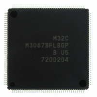
M3087BFLBGP#U5 Renesas Electronics America, M3087BFLBGP#U5 Datasheet - Page 626

M3087BFLBGP#U5
Manufacturer Part Number
M3087BFLBGP#U5
Description
IC M32C/87 MCU FLASH 144LQFP
Manufacturer
Renesas Electronics America
Series
M16C™ M32C/80r
Datasheet
1.M3087BFLGPU3.pdf
(629 pages)
Specifications of M3087BFLBGP#U5
Core Processor
M32C/80
Core Size
16/32-Bit
Speed
32MHz
Connectivity
EBI/EMI, I²C, IEBus, IrDA, SIO, UART/USART
Peripherals
DMA, POR, PWM, WDT
Number Of I /o
121
Program Memory Size
1MB (1M x 8)
Program Memory Type
FLASH
Ram Size
48K x 8
Voltage - Supply (vcc/vdd)
3 V ~ 5.5 V
Data Converters
A/D 34x10b, D/A 2x8b
Oscillator Type
Internal
Operating Temperature
-20°C ~ 85°C
Package / Case
144-LQFP
For Use With
R0K330879S001BE - KIT DEV RSK M32C/87R0K330879S000BE - KIT DEV RSK M32C/87
Lead Free Status / RoHS Status
Lead free / RoHS Compliant
Eeprom Size
-
Available stocks
Company
Part Number
Manufacturer
Quantity
Price
Part Number:
M3087BFLBGP#U5M3087BFLBGP#U3
Manufacturer:
Renesas Electronics America
Quantity:
10 000
- Current page: 626 of 629
- Download datasheet (16Mb)
Rev.
REVISION HISTORY
1.51
Jul 31, 2008
Date
99, 102
Page
101
104
110
110
121
134
139
187
195
201
203
242
243
266
19
21
46
57
81
91
93
97
97
98
−
All in this manual
Overview
• 1.5 Pin Descriptions Chapter and table title changed to Pin Functions
• Table 1.17 Supply voltage for
Special Function Registers (SFRs)
• Table 4.20 A value of After Reset column in 03FFh modified
Power Supply Voltage Detection Circuit
• Figure 6.6 NOTE 1 “internal VDC” changed to “the main voltage regulator”
Clock Generation Function
• Figure 9.1 “Charge pump” changed to “Loop filter”
• Table 9.2 “(The clock keeps running in stop mode)” deleted
• 9.1.4 PLL Clock Text partly revised
• 9.5.1.3 Low-Speed Mode Text partly revised
• 9.5.1.4 Low-Power Consumption Mode Text partly revised
• Table 9.6 Values of “-” in bits CM21 and CM17 in the Sub Clock row and
• Figure 9.14 and 9.15 Note 1 partly modified
• Table 9.8 Word “the clock input to the CLKi pin (i = 0 to 6)” changed to “the
• 9.6 System Clock Protect Function and Figure 9.16 Text partly revised
Interrupts
• 11.5.1 Fixed Vector Table Text partly revised
• Table 11.1 Reference in the Watchdog timer row, “Reset” changed to
• Figure 11.10 “Interrupt request priority level detection result” changed to
Watchdog Timer
• Table 12.2 Values in WDC7 bit in WDC register revised
DMAC
• Table 13.1 “DMA stop condition” modified
Timer
• Figure 15.24 NOTE 3 “a 0” deleted
• Figure 15.30 NOTE 3 “a 0” deleted
Three-Phase Motor Control Timer Function
• Figure 16.5 Value in operating mode select bits column “01b” changed to
• Figure 16.7 Function column of ICTB2 register
Serial Interfaces
• Table 17.7 NOTE 3 Sentence of “The IR bit in the SiRIC register...” deleted
• Figure 17.23 “IICM2 = 1” changed to “IICM = 0 or IICM2 = 1”
• Figure 17.33 The sentence “m:setting value of the UiBRG register” added
[pin and bit symbol notation modified]
[description modified]
“Voltage detection”
“Interrupt request level determination”
“10b”
In the sentence “When bits INV01 and INV00 are set to 11b ”, two cases of
when n > 1 and when n = 1 are added subsequently
in CM17 bit in the On-chip oscillator mode row changed to “0”
external clock”
• P5_5(EPM) → EPM(P5_5)
• P5_0(CE) → CE(P5_0)
• PM04, PM05 → PM05 and PM04
• Title of group tables “(current table number / total tables)” added
M32C/87 Group Hardware Manual
C - 15
Description
AN0_0 to AN0_7, AN2_0 to AN2_7
Summary
modified
Related parts for M3087BFLBGP#U5
Image
Part Number
Description
Manufacturer
Datasheet
Request
R

Part Number:
Description:
KIT STARTER FOR M16C/29
Manufacturer:
Renesas Electronics America
Datasheet:

Part Number:
Description:
KIT STARTER FOR R8C/2D
Manufacturer:
Renesas Electronics America
Datasheet:

Part Number:
Description:
R0K33062P STARTER KIT
Manufacturer:
Renesas Electronics America
Datasheet:

Part Number:
Description:
KIT STARTER FOR R8C/23 E8A
Manufacturer:
Renesas Electronics America
Datasheet:

Part Number:
Description:
KIT STARTER FOR R8C/25
Manufacturer:
Renesas Electronics America
Datasheet:

Part Number:
Description:
KIT STARTER H8S2456 SHARPE DSPLY
Manufacturer:
Renesas Electronics America
Datasheet:

Part Number:
Description:
KIT STARTER FOR R8C38C
Manufacturer:
Renesas Electronics America
Datasheet:

Part Number:
Description:
KIT STARTER FOR R8C35C
Manufacturer:
Renesas Electronics America
Datasheet:

Part Number:
Description:
KIT STARTER FOR R8CL3AC+LCD APPS
Manufacturer:
Renesas Electronics America
Datasheet:

Part Number:
Description:
KIT STARTER FOR RX610
Manufacturer:
Renesas Electronics America
Datasheet:

Part Number:
Description:
KIT STARTER FOR R32C/118
Manufacturer:
Renesas Electronics America
Datasheet:

Part Number:
Description:
KIT DEV RSK-R8C/26-29
Manufacturer:
Renesas Electronics America
Datasheet:

Part Number:
Description:
KIT STARTER FOR SH7124
Manufacturer:
Renesas Electronics America
Datasheet:

Part Number:
Description:
KIT STARTER FOR H8SX/1622
Manufacturer:
Renesas Electronics America
Datasheet:

Part Number:
Description:
KIT DEV FOR SH7203
Manufacturer:
Renesas Electronics America
Datasheet:


