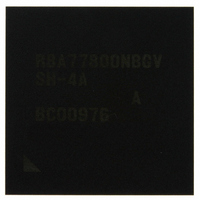
R8A77800ANBGAV Renesas Electronics America, R8A77800ANBGAV Datasheet - Page 36

R8A77800ANBGAV
Manufacturer Part Number
R8A77800ANBGAV
Description
IC SUPERH MPU ROMLESS 449-BGA
Manufacturer
Renesas Electronics America
Series
SuperH® SH7780r
Datasheet
1.R8A77800ANBGV.pdf
(1342 pages)
Specifications of R8A77800ANBGAV
Core Processor
SH-4A
Core Size
32-Bit
Speed
400MHz
Connectivity
Audio Codec, MMC, Serial Sound, SCI, SIO, SPI, SSI
Peripherals
DMA, POR, WDT
Number Of I /o
75
Program Memory Type
ROMless
Ram Size
16K x 8
Voltage - Supply (vcc/vdd)
1.15 V ~ 1.35 V
Oscillator Type
External
Operating Temperature
-20°C ~ 75°C
Package / Case
449-BGA
Lead Free Status / RoHS Status
Lead free / RoHS Compliant
Eeprom Size
-
Program Memory Size
-
Data Converters
-
Available stocks
Company
Part Number
Manufacturer
Quantity
Price
Company:
Part Number:
R8A77800ANBGAV
Manufacturer:
Renesas Electronics America
Quantity:
10 000
- Current page: 36 of 1342
- Download datasheet (7Mb)
Section 15 Clock Pulse Generator (CPG)
Figure 15.1 Block Diagram of CPG ........................................................................................... 614
Figure 15.2 Points for Attention when Using Crystal Resonator................................................ 622
Figure 15.3 Points for Attention when Using PLL and DLL Circuit.......................................... 623
Section 16 Watchdog Timer and Reset
Figure 16.1 Block Diagram of WDT .......................................................................................... 626
Figure 16.2 WDT Counting Up Operation ................................................................................. 635
Figure 16.3 STATUS Output during Power-on.......................................................................... 637
Figure 16.4 STATUS Output by Reset input during Normal Operation .................................... 637
Figure 16.5 STATUS Output by Reset input during Sleep Mode .............................................. 638
Figure 16.6 STATUS Output by Watchdog timer overflow Power-On Reset
Figure 16.7 STATUS Output by Watchdog timer overflow Power-On Reset
Figure 16.8 STATUS Output by Watchdog timer overflow Manual Reset
Figure 16.9 STATUS Output by Watchdog timer overflow Manual Reset
Section 17 Power-Down Mode
Figure 17.1 DDR-SDRAM Interface Operation when
Figure 17.2 Sequence for Turning Off System Power Supply in Self-Refresh Mode ................ 652
Figure 17.3 Sequence for Turning System Power Supply On/Off.............................................. 654
Figure 17.4 Mode Transition Diagram ....................................................................................... 655
Figure 17.5 Status Pins Output from Sleep to Interrupt.............................................................. 656
Section 18 Timer Unit (TMU)
Figure 18.1 Block Diagram of TMU .......................................................................................... 658
Figure 18.2 Example of Count Operation Setting Procedure ..................................................... 670
Figure 18.3 TCNT Auto-Reload Operation ................................................................................ 671
Figure 18.4 Count Timing when Operating on Internal Clock ................................................... 671
Figure 18.5 Count Timing when Operating on External Clock .................................................. 672
Figure 18.6 Count Timing when Operating on on-chip RTC output Clock ............................... 672
Figure 18.7 Operation Timing when Using Input Capture Function .......................................... 673
Section 19 Timer/Counter (CMT)
Figure 19.1 Block Diagram of CMT .......................................................................................... 678
Figure 19.2 Edge Detection (example of rising edge) ................................................................ 691
Figure 19.3 32-Bit Timer Mode: Input Capture (channel 1 and channel 0)................................ 692
Figure 19.4 32-bit Timer mode: Input Capture Operation Timing ............................................. 692
Rev.1.00 Dec. 13, 2005 Page xxxiv of l
during Normal Operation ........................................................................................ 639
during Sleep Mode .................................................................................................. 639
Turning System Power Supply On/Off ................................................................... 650
during Normal Operation........................................................................................ 640
during Sleep Mode.................................................................................................. 641
Related parts for R8A77800ANBGAV
Image
Part Number
Description
Manufacturer
Datasheet
Request
R

Part Number:
Description:
KIT STARTER FOR M16C/29
Manufacturer:
Renesas Electronics America
Datasheet:

Part Number:
Description:
KIT STARTER FOR R8C/2D
Manufacturer:
Renesas Electronics America
Datasheet:

Part Number:
Description:
R0K33062P STARTER KIT
Manufacturer:
Renesas Electronics America
Datasheet:

Part Number:
Description:
KIT STARTER FOR R8C/23 E8A
Manufacturer:
Renesas Electronics America
Datasheet:

Part Number:
Description:
KIT STARTER FOR R8C/25
Manufacturer:
Renesas Electronics America
Datasheet:

Part Number:
Description:
KIT STARTER H8S2456 SHARPE DSPLY
Manufacturer:
Renesas Electronics America
Datasheet:

Part Number:
Description:
KIT STARTER FOR R8C38C
Manufacturer:
Renesas Electronics America
Datasheet:

Part Number:
Description:
KIT STARTER FOR R8C35C
Manufacturer:
Renesas Electronics America
Datasheet:

Part Number:
Description:
KIT STARTER FOR R8CL3AC+LCD APPS
Manufacturer:
Renesas Electronics America
Datasheet:

Part Number:
Description:
KIT STARTER FOR RX610
Manufacturer:
Renesas Electronics America
Datasheet:

Part Number:
Description:
KIT STARTER FOR R32C/118
Manufacturer:
Renesas Electronics America
Datasheet:

Part Number:
Description:
KIT DEV RSK-R8C/26-29
Manufacturer:
Renesas Electronics America
Datasheet:

Part Number:
Description:
KIT STARTER FOR SH7124
Manufacturer:
Renesas Electronics America
Datasheet:

Part Number:
Description:
KIT STARTER FOR H8SX/1622
Manufacturer:
Renesas Electronics America
Datasheet:

Part Number:
Description:
KIT DEV FOR SH7203
Manufacturer:
Renesas Electronics America
Datasheet:


