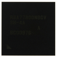
R8A77800ANBGAV Renesas Electronics America, R8A77800ANBGAV Datasheet - Page 386

R8A77800ANBGAV
Manufacturer Part Number
R8A77800ANBGAV
Description
IC SUPERH MPU ROMLESS 449-BGA
Manufacturer
Renesas Electronics America
Series
SuperH® SH7780r
Datasheet
1.R8A77800ANBGV.pdf
(1342 pages)
Specifications of R8A77800ANBGAV
Core Processor
SH-4A
Core Size
32-Bit
Speed
400MHz
Connectivity
Audio Codec, MMC, Serial Sound, SCI, SIO, SPI, SSI
Peripherals
DMA, POR, WDT
Number Of I /o
75
Program Memory Type
ROMless
Ram Size
16K x 8
Voltage - Supply (vcc/vdd)
1.15 V ~ 1.35 V
Oscillator Type
External
Operating Temperature
-20°C ~ 75°C
Package / Case
449-BGA
Lead Free Status / RoHS Status
Lead free / RoHS Compliant
Eeprom Size
-
Program Memory Size
-
Data Converters
-
Available stocks
Company
Part Number
Manufacturer
Quantity
Price
Company:
Part Number:
R8A77800ANBGAV
Manufacturer:
Renesas Electronics America
Quantity:
10 000
- Current page: 386 of 1342
- Download datasheet (7Mb)
Section 11 Local Bus State Controller (LBSC)
Rev.1.00 Dec. 13, 2005 Page 334 of 1286
REJ09B0158-0100
Bit
26
25
24
23 to 20 DACKBST
Bit Name
DPUP
OPUP
[3:0]
Initial
Value
0
0
0
All 0
R/W
R/W
R
R/W
R/W
Description
Data Pin Pull-Up Resistor Control
Specifies the pull-up resistor state of the data pins (D31
to D0). This bit is initialized by a power-on reset. The
pins are not pulled up when access is performed or
when the bus is released, even if the pull-up resistor is
on.
0: Cycles in which the pull-up resistors of the data pins
1: Pull-up resistor is off for data pins (D31 to D0).
Note: * We recommend that a pull-up resistor be
Reserved
This bit is always read as 0. The write value should
always be 0.
Control Output Pin Pull-Up Resistor Control
Specifies the pull-up resistor state (A25 to A0, BS, CS0
to CS2, CS4 to CS6, RD/FRAME, WE, R/W, CE2A, and
CE2B) when the control output pins are high-
impedance. This bit is initialized by a power-on reset.
0: Pull-up resistors are on for control output pins (A25 to
1: Pull-up resistors are off for control output pins (A25 to
DACK Burst
Select the assert period of DACK0 to DACK3 signals.
0: DACK signals asserted in synchronization with the
1: DACK signals remain asserted from burst start to end
Only set to 1 when the area of a DACK assertion in
DMA transfer is the PCMCIA interface memory area,
otherwise this bit should be cleared to 0.
DACKBST[3]: DACK3
DACKBST[2]: DACK2
DACKBST[1]: DACK1
DACKBST[0]: DACK0
in DMA burst transfer mode
bus cycle.
(D31 to D0) are turned on are inserted before and
after a memory access.*
A0, BS, CS0 to CS2, CS4 to CS6, RD/FRAME, WE,
R/W, CE2A, and CE2B)
A0, BS, CS0 to CS2, CS4 to CS6, RD/FRAME, WE,
R/W, CE2A, and CE2B)
externally connected to the data pins if it is
required.
Related parts for R8A77800ANBGAV
Image
Part Number
Description
Manufacturer
Datasheet
Request
R

Part Number:
Description:
KIT STARTER FOR M16C/29
Manufacturer:
Renesas Electronics America
Datasheet:

Part Number:
Description:
KIT STARTER FOR R8C/2D
Manufacturer:
Renesas Electronics America
Datasheet:

Part Number:
Description:
R0K33062P STARTER KIT
Manufacturer:
Renesas Electronics America
Datasheet:

Part Number:
Description:
KIT STARTER FOR R8C/23 E8A
Manufacturer:
Renesas Electronics America
Datasheet:

Part Number:
Description:
KIT STARTER FOR R8C/25
Manufacturer:
Renesas Electronics America
Datasheet:

Part Number:
Description:
KIT STARTER H8S2456 SHARPE DSPLY
Manufacturer:
Renesas Electronics America
Datasheet:

Part Number:
Description:
KIT STARTER FOR R8C38C
Manufacturer:
Renesas Electronics America
Datasheet:

Part Number:
Description:
KIT STARTER FOR R8C35C
Manufacturer:
Renesas Electronics America
Datasheet:

Part Number:
Description:
KIT STARTER FOR R8CL3AC+LCD APPS
Manufacturer:
Renesas Electronics America
Datasheet:

Part Number:
Description:
KIT STARTER FOR RX610
Manufacturer:
Renesas Electronics America
Datasheet:

Part Number:
Description:
KIT STARTER FOR R32C/118
Manufacturer:
Renesas Electronics America
Datasheet:

Part Number:
Description:
KIT DEV RSK-R8C/26-29
Manufacturer:
Renesas Electronics America
Datasheet:

Part Number:
Description:
KIT STARTER FOR SH7124
Manufacturer:
Renesas Electronics America
Datasheet:

Part Number:
Description:
KIT STARTER FOR H8SX/1622
Manufacturer:
Renesas Electronics America
Datasheet:

Part Number:
Description:
KIT DEV FOR SH7203
Manufacturer:
Renesas Electronics America
Datasheet:


