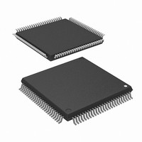
R5F2L3AAANFP#U1 Renesas Electronics America, R5F2L3AAANFP#U1 Datasheet - Page 15

R5F2L3AAANFP#U1
Manufacturer Part Number
R5F2L3AAANFP#U1
Description
MCU FLASH 96+4KB 100LQFP
Manufacturer
Renesas Electronics America
Series
R8C/Lx/3AAr
Datasheet
1.R5F2L387ANFPU1.pdf
(864 pages)
Specifications of R5F2L3AAANFP#U1
Core Processor
R8C
Core Size
16/32-Bit
Speed
20MHz
Connectivity
I²C, LIN, SIO, SSU, UART/USART
Peripherals
LCD, POR, PWM, Voltage Detect, WDT
Number Of I /o
88
Program Memory Size
96KB (96K x 8)
Program Memory Type
FLASH
Ram Size
10K x 8
Voltage - Supply (vcc/vdd)
1.8 V ~ 5.5 V
Data Converters
A/D 20x10b; D/A 2x8b
Oscillator Type
Internal
Operating Temperature
-20°C ~ 85°C
Package / Case
100-LQFP
Lead Free Status / RoHS Status
Lead free / RoHS Compliant
Eeprom Size
-
Available stocks
Company
Part Number
Manufacturer
Quantity
Price
- Current page: 15 of 864
- Download datasheet (16Mb)
16.
17.
15.3
15.4
17.1
17.2
17.3
17.4
17.5
17.6
17.7
17.8
15.2.3
15.2.4
15.2.5
15.2.6
15.2.7
15.2.8
15.3.1
15.3.2
15.3.3
15.3.4
15.3.5
15.3.6
15.3.7
15.3.8
15.3.9
15.3.10 DTC Activation Source Acknowledgement and Interrupt Source Flags .......................................... 216
15.4.1
15.4.2
15.4.3
15.4.4
17.2.1
17.2.2
17.2.3
17.2.4
17.2.5
17.2.6
17.3.1
17.3.2
17.4.1
17.5.1
17.6.1
17.6.2
17.7.1
17.7.2
Timers ......................................................................................................................................... 218
Timer RA ..................................................................................................................................... 220
Function Description ............................................................................................................................. 204
Notes on DTC ........................................................................................................................................ 217
Introduction ........................................................................................................................................... 220
Registers ................................................................................................................................................ 221
Timer Mode ........................................................................................................................................... 224
Pulse Output Mode ................................................................................................................................ 226
Event Counter Mode ............................................................................................................................. 228
Pulse Width Measurement Mode .......................................................................................................... 230
Pulse Period Measurement Mode .......................................................................................................... 233
Notes on Timer RA ............................................................................................................................... 236
DTC Transfer Count Register j (DTCCTj) (j = 0 to 23) ................................................................... 201
DTC Transfer Count Reload Register j (DTRLDj) (j = 0 to 23) ...................................................... 201
DTC Source Address Register j (DTSARj) (j = 0 to 23) .................................................................. 201
DTC Destination Register j (DTDARj) (j = 0 to 23) ........................................................................ 201
DTC Activation Enable Register i (DTCENi) (i = 0 to 6) ................................................................ 202
DTC Activation Control Register (DTCTL) .................................................................................... 203
Overview ........................................................................................................................................... 204
Activation Sources ............................................................................................................................ 204
Control Data Allocation and DTC Vector Table .............................................................................. 206
Normal Mode .................................................................................................................................... 211
Repeat Mode ..................................................................................................................................... 212
Chain Transfers ................................................................................................................................. 213
Interrupt Sources ............................................................................................................................... 213
Operation Timings ............................................................................................................................ 214
Number of DTC Execution Cycles ................................................................................................... 215
DTC activation source ...................................................................................................................... 217
DTCENi (i = 0 to 6) Registers .......................................................................................................... 217
Peripheral Modules ........................................................................................................................... 217
Interrupt Request ............................................................................................................................... 217
Timer RA Control Register (TRACR) .............................................................................................. 221
Timer RA I/O Control Register (TRAIOC) ...................................................................................... 221
Timer RA Mode Register (TRAMR) ................................................................................................ 222
Timer RA Prescaler Register (TRAPRE) ......................................................................................... 222
Timer RA Register (TRA) ................................................................................................................ 223
Timer RA Pin Select Register (TRASR) .......................................................................................... 223
Timer RA I/O Control Register (TRAIOC) in Timer Mode ............................................................ 224
Timer Write Control during Count Operation .................................................................................. 225
Timer RA I/O Control Register (TRAIOC) in Pulse Output Mode ................................................. 227
Timer RA I/O Control Register (TRAIOC) in Event Counter Mode ............................................... 229
Timer RA I/O Control Register (TRAIOC) in Pulse Width Measurement Mode ............................ 231
Operating Example ........................................................................................................................... 232
Timer RA I/O Control Register (TRAIOC) in Pulse Period Measurement Mode ........................... 234
Operating Example ........................................................................................................................... 235
A - 6
Related parts for R5F2L3AAANFP#U1
Image
Part Number
Description
Manufacturer
Datasheet
Request
R

Part Number:
Description:
KIT STARTER FOR M16C/29
Manufacturer:
Renesas Electronics America
Datasheet:

Part Number:
Description:
KIT STARTER FOR R8C/2D
Manufacturer:
Renesas Electronics America
Datasheet:

Part Number:
Description:
R0K33062P STARTER KIT
Manufacturer:
Renesas Electronics America
Datasheet:

Part Number:
Description:
KIT STARTER FOR R8C/23 E8A
Manufacturer:
Renesas Electronics America
Datasheet:

Part Number:
Description:
KIT STARTER FOR R8C/25
Manufacturer:
Renesas Electronics America
Datasheet:

Part Number:
Description:
KIT STARTER H8S2456 SHARPE DSPLY
Manufacturer:
Renesas Electronics America
Datasheet:

Part Number:
Description:
KIT STARTER FOR R8C38C
Manufacturer:
Renesas Electronics America
Datasheet:

Part Number:
Description:
KIT STARTER FOR R8C35C
Manufacturer:
Renesas Electronics America
Datasheet:

Part Number:
Description:
KIT STARTER FOR R8CL3AC+LCD APPS
Manufacturer:
Renesas Electronics America
Datasheet:

Part Number:
Description:
KIT STARTER FOR RX610
Manufacturer:
Renesas Electronics America
Datasheet:

Part Number:
Description:
KIT STARTER FOR R32C/118
Manufacturer:
Renesas Electronics America
Datasheet:

Part Number:
Description:
KIT DEV RSK-R8C/26-29
Manufacturer:
Renesas Electronics America
Datasheet:

Part Number:
Description:
KIT STARTER FOR SH7124
Manufacturer:
Renesas Electronics America
Datasheet:

Part Number:
Description:
KIT STARTER FOR H8SX/1622
Manufacturer:
Renesas Electronics America
Datasheet:

Part Number:
Description:
KIT DEV FOR SH7203
Manufacturer:
Renesas Electronics America
Datasheet:


