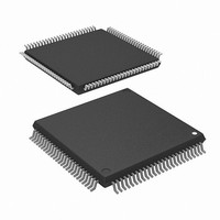
R5F2L3AAANFP#U1 Renesas Electronics America, R5F2L3AAANFP#U1 Datasheet - Page 630

R5F2L3AAANFP#U1
Manufacturer Part Number
R5F2L3AAANFP#U1
Description
MCU FLASH 96+4KB 100LQFP
Manufacturer
Renesas Electronics America
Series
R8C/Lx/3AAr
Datasheet
1.R5F2L387ANFPU1.pdf
(864 pages)
Specifications of R5F2L3AAANFP#U1
Core Processor
R8C
Core Size
16/32-Bit
Speed
20MHz
Connectivity
I²C, LIN, SIO, SSU, UART/USART
Peripherals
LCD, POR, PWM, Voltage Detect, WDT
Number Of I /o
88
Program Memory Size
96KB (96K x 8)
Program Memory Type
FLASH
Ram Size
10K x 8
Voltage - Supply (vcc/vdd)
1.8 V ~ 5.5 V
Data Converters
A/D 20x10b; D/A 2x8b
Oscillator Type
Internal
Operating Temperature
-20°C ~ 85°C
Package / Case
100-LQFP
Lead Free Status / RoHS Status
Lead free / RoHS Compliant
Eeprom Size
-
Available stocks
Company
Part Number
Manufacturer
Quantity
Price
- Current page: 630 of 864
- Download datasheet (16Mb)
R8C/L35A Group, R8C/L36A Group, R8C/L38A Group, R8C/L3AA Group,
R8C/L35B Group, R8C/L36B Group, R8C/L38B Group, R8C/L3AB Group
REJ09B0441-0100 Rev.1.00
Page 593 of 802
27.3.3
Table 27.6
STIE, NAKIE, RIE, TEIE, TIE: Bits in ICIER register
AL, STOP, NACKF, RDRF, TEND, TDRE: Bits in ICSR register
Transmit data empty
Transmit end
Receive data full
Stop condition detection
NACK detection
Arbitration lost/overrun error
The I
the clock synchronous serial format is used.
Table 27.6 lists the Interrupt Requests of I
Because these interrupt requests are allocated at the I
determined bit by bit.
When generation conditions listed in Table 27.6 are met, an interrupt request of the I
generated. Set the interrupt generation conditions to 0 by the I
However, bits TDRE and TEND are automatically set to 0 by writing transmit data to the ICDRT register and
the RDRF bit is automatically set to 0 by reading the ICDRR register. In particular, the TDRE bit is set to 0
when transmit data is written to the ICDRT register and set to 1 when data is transferred from the ICDRT
register to the ICDRS register. If the TDRE bit is further set to 0, additional 1 byte may be transmitted.
Also, set the STIE bit to 1 (stop condition detection interrupt request enabled) when the STOP bit is set to 0.
2
C bus interface has six interrupt requests when the I
Interrupt Requests
Interrupt Request
Interrupt Requests of I
Oct 30, 2009
TXI
TEI
RXI
STPI
NAKI
2
C bus Interface
2
C bus Interface.
TIE = 1 and TDRE = 1
TEIE = 1 and TEND = 1
RIE = 1 and RDRF = 1
STIE = 1 and STOP = 1
NAKIE = 1 and AL = 1
(or NAKIE = 1 and NACKF = 1)
Generation Condition
2
C bus interface interrupt vector table, the source must be
2
C bus format is used and four interrupt requests when
2
C bus interface interrupt routine.
Enabled
Enabled
Enabled
Enabled
Enabled
Enabled
I
2
C bus
27. I
2
Format
C bus interface is
2
Synchronous
Enabled
Enabled
Enabled
Disabled
Disabled
Enabled
C bus Interface
Clock
Serial
Related parts for R5F2L3AAANFP#U1
Image
Part Number
Description
Manufacturer
Datasheet
Request
R

Part Number:
Description:
KIT STARTER FOR M16C/29
Manufacturer:
Renesas Electronics America
Datasheet:

Part Number:
Description:
KIT STARTER FOR R8C/2D
Manufacturer:
Renesas Electronics America
Datasheet:

Part Number:
Description:
R0K33062P STARTER KIT
Manufacturer:
Renesas Electronics America
Datasheet:

Part Number:
Description:
KIT STARTER FOR R8C/23 E8A
Manufacturer:
Renesas Electronics America
Datasheet:

Part Number:
Description:
KIT STARTER FOR R8C/25
Manufacturer:
Renesas Electronics America
Datasheet:

Part Number:
Description:
KIT STARTER H8S2456 SHARPE DSPLY
Manufacturer:
Renesas Electronics America
Datasheet:

Part Number:
Description:
KIT STARTER FOR R8C38C
Manufacturer:
Renesas Electronics America
Datasheet:

Part Number:
Description:
KIT STARTER FOR R8C35C
Manufacturer:
Renesas Electronics America
Datasheet:

Part Number:
Description:
KIT STARTER FOR R8CL3AC+LCD APPS
Manufacturer:
Renesas Electronics America
Datasheet:

Part Number:
Description:
KIT STARTER FOR RX610
Manufacturer:
Renesas Electronics America
Datasheet:

Part Number:
Description:
KIT STARTER FOR R32C/118
Manufacturer:
Renesas Electronics America
Datasheet:

Part Number:
Description:
KIT DEV RSK-R8C/26-29
Manufacturer:
Renesas Electronics America
Datasheet:

Part Number:
Description:
KIT STARTER FOR SH7124
Manufacturer:
Renesas Electronics America
Datasheet:

Part Number:
Description:
KIT STARTER FOR H8SX/1622
Manufacturer:
Renesas Electronics America
Datasheet:

Part Number:
Description:
KIT DEV FOR SH7203
Manufacturer:
Renesas Electronics America
Datasheet:


