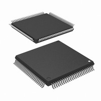
R5F2L3AAANFP#U1 Renesas Electronics America, R5F2L3AAANFP#U1 Datasheet - Page 22

R5F2L3AAANFP#U1
Manufacturer Part Number
R5F2L3AAANFP#U1
Description
MCU FLASH 96+4KB 100LQFP
Manufacturer
Renesas Electronics America
Series
R8C/Lx/3AAr
Datasheet
1.R5F2L387ANFPU1.pdf
(864 pages)
Specifications of R5F2L3AAANFP#U1
Core Processor
R8C
Core Size
16/32-Bit
Speed
20MHz
Connectivity
I²C, LIN, SIO, SSU, UART/USART
Peripherals
LCD, POR, PWM, Voltage Detect, WDT
Number Of I /o
88
Program Memory Size
96KB (96K x 8)
Program Memory Type
FLASH
Ram Size
10K x 8
Voltage - Supply (vcc/vdd)
1.8 V ~ 5.5 V
Data Converters
A/D 20x10b; D/A 2x8b
Oscillator Type
Internal
Operating Temperature
-20°C ~ 85°C
Package / Case
100-LQFP
Lead Free Status / RoHS Status
Lead free / RoHS Compliant
Eeprom Size
-
Available stocks
Company
Part Number
Manufacturer
Quantity
Price
- Current page: 22 of 864
- Download datasheet (16Mb)
24.
23.3
23.4
23.5
24.1
24.2
24.3
24.4
24.5
23.2.4
23.2.5
23.2.6
23.2.7
23.2.8
23.3.1
23.3.2
23.3.3
23.3.4
23.4.1
23.4.2
24.2.1
24.2.2
24.2.3
24.2.4
24.2.5
24.2.6
24.2.7
24.2.8
24.2.9
24.2.10 UART2 Special Mode Register 3 (U2SMR3) .................................................................................. 507
24.2.11 UART2 Special Mode Register 2 (U2SMR2) .................................................................................. 508
24.2.12 UART2 Special Mode Register (U2SMR) ....................................................................................... 508
24.2.13 UART2 Pin Select Register 0 (U2SR0) ............................................................................................ 509
24.2.14 UART2 Pin Select Register 1 (U2SR1) ............................................................................................ 510
24.3.1
24.3.2
24.3.3
24.3.4
24.3.5
24.3.6
24.4.1
24.4.2
24.4.3
24.4.4
24.4.5
24.4.6
24.4.7
24.5.1
Serial Interface (UART2) ............................................................................................................ 499
Clock Synchronous Serial I/O Mode ..................................................................................................... 485
Clock Asynchronous Serial I/O (UART) Mode .................................................................................... 491
Notes on Serial Interface (UARTi (i = 0 or 1)) ..................................................................................... 498
Introduction ........................................................................................................................................... 499
Registers ................................................................................................................................................ 501
Clock Synchronous Serial I/O Mode ..................................................................................................... 511
Clock Asynchronous Serial I/O (UART) Mode .................................................................................... 519
Special Mode 1 (I
UARTi Transmit/Receive Control Register 0 (UiC0) (i = 0 or 1) .................................................... 481
UARTi Transmit/Receive Control Register 1 (UiC1) (i = 0 or 1) .................................................... 481
UARTi Receive Buffer Register (UiRB) (i = 0 or 1) ....................................................................... 482
UART0 Pin Select Register (U0SR) ................................................................................................. 483
UART1 Pin Select Register (U1SR) ................................................................................................. 484
Measure for Dealing with Communication Errors ........................................................................... 489
Polarity Select Function .................................................................................................................... 489
LSB First/MSB First Select Function ............................................................................................... 490
Continuous Receive Mode ................................................................................................................ 490
Bit Rate ............................................................................................................................................. 496
Measure for Dealing with Communication Errors ........................................................................... 497
UART2 Transmit/Receive Mode Register (U2MR) ......................................................................... 501
UART2 Bit Rate Register (U2BRG) ................................................................................................ 501
UART2 Transmit Buffer Register (U2TB) ....................................................................................... 502
UART2 Transmit/Receive Control Register 0 (U2C0) .................................................................... 503
UART2 Transmit/Receive Control Register 1 (U2C1) .................................................................... 504
UART2 Receive Buffer Register (U2RB) ........................................................................................ 505
UART2 Digital Filter Function Select Register (URXDF) .............................................................. 506
UART2 Special Mode Register 5 (U2SMR5) .................................................................................. 506
UART2 Special Mode Register 4 (U2SMR4) .................................................................................. 507
Measure for Dealing with Communication Errors ........................................................................... 515
CLK Polarity Select Function ........................................................................................................... 515
LSB First/MSB First Select Function ............................................................................................... 516
Continuous Receive Mode ................................................................................................................ 516
Serial Data Logic Switching Function .............................................................................................. 517
CTS/RTS Function ............................................................................................................................ 518
Bit Rate ............................................................................................................................................. 523
Measure for Dealing with Communication Errors ........................................................................... 524
LSB First/MSB First Select Function ............................................................................................... 524
Serial Data Logic Switching Function .............................................................................................. 525
TXD and RXD I/O Polarity Inverse Function .................................................................................. 525
CTS/RTS Function ............................................................................................................................ 526
RXD2 Digital Filter Select Function ................................................................................................ 526
Detection of Start and Stop Conditions ............................................................................................ 533
2
C Mode) .................................................................................................................. 527
A - 13
Related parts for R5F2L3AAANFP#U1
Image
Part Number
Description
Manufacturer
Datasheet
Request
R

Part Number:
Description:
KIT STARTER FOR M16C/29
Manufacturer:
Renesas Electronics America
Datasheet:

Part Number:
Description:
KIT STARTER FOR R8C/2D
Manufacturer:
Renesas Electronics America
Datasheet:

Part Number:
Description:
R0K33062P STARTER KIT
Manufacturer:
Renesas Electronics America
Datasheet:

Part Number:
Description:
KIT STARTER FOR R8C/23 E8A
Manufacturer:
Renesas Electronics America
Datasheet:

Part Number:
Description:
KIT STARTER FOR R8C/25
Manufacturer:
Renesas Electronics America
Datasheet:

Part Number:
Description:
KIT STARTER H8S2456 SHARPE DSPLY
Manufacturer:
Renesas Electronics America
Datasheet:

Part Number:
Description:
KIT STARTER FOR R8C38C
Manufacturer:
Renesas Electronics America
Datasheet:

Part Number:
Description:
KIT STARTER FOR R8C35C
Manufacturer:
Renesas Electronics America
Datasheet:

Part Number:
Description:
KIT STARTER FOR R8CL3AC+LCD APPS
Manufacturer:
Renesas Electronics America
Datasheet:

Part Number:
Description:
KIT STARTER FOR RX610
Manufacturer:
Renesas Electronics America
Datasheet:

Part Number:
Description:
KIT STARTER FOR R32C/118
Manufacturer:
Renesas Electronics America
Datasheet:

Part Number:
Description:
KIT DEV RSK-R8C/26-29
Manufacturer:
Renesas Electronics America
Datasheet:

Part Number:
Description:
KIT STARTER FOR SH7124
Manufacturer:
Renesas Electronics America
Datasheet:

Part Number:
Description:
KIT STARTER FOR H8SX/1622
Manufacturer:
Renesas Electronics America
Datasheet:

Part Number:
Description:
KIT DEV FOR SH7203
Manufacturer:
Renesas Electronics America
Datasheet:


