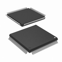
R5F2L3AAANFP#U1 Renesas Electronics America, R5F2L3AAANFP#U1 Datasheet - Page 17

R5F2L3AAANFP#U1
Manufacturer Part Number
R5F2L3AAANFP#U1
Description
MCU FLASH 96+4KB 100LQFP
Manufacturer
Renesas Electronics America
Series
R8C/Lx/3AAr
Datasheet
1.R5F2L387ANFPU1.pdf
(864 pages)
Specifications of R5F2L3AAANFP#U1
Core Processor
R8C
Core Size
16/32-Bit
Speed
20MHz
Connectivity
I²C, LIN, SIO, SSU, UART/USART
Peripherals
LCD, POR, PWM, Voltage Detect, WDT
Number Of I /o
88
Program Memory Size
96KB (96K x 8)
Program Memory Type
FLASH
Ram Size
10K x 8
Voltage - Supply (vcc/vdd)
1.8 V ~ 5.5 V
Data Converters
A/D 20x10b; D/A 2x8b
Oscillator Type
Internal
Operating Temperature
-20°C ~ 85°C
Package / Case
100-LQFP
Lead Free Status / RoHS Status
Lead free / RoHS Compliant
Eeprom Size
-
Available stocks
Company
Part Number
Manufacturer
Quantity
Price
- Current page: 17 of 864
- Download datasheet (16Mb)
20.
19.3
19.4
19.5
19.6
19.7
19.8
19.9
20.1
20.2
20.3
19.3.1
19.3.2
19.3.3
19.3.4
19.4.1
19.4.2
19.4.3
19.5.1
19.5.2
19.5.3
19.5.4
19.5.5
19.5.6
19.6.1
19.6.2
19.6.3
19.7.1
19.7.2
19.7.3
19.7.4
19.9.1
19.9.2
19.9.3
19.9.4
19.9.5
20.2.1
20.2.2
20.2.3
20.2.4
20.3.1
20.3.2
20.3.3
20.3.4
20.3.5
20.3.6
20.3.7
Timer RD ..................................................................................................................................... 308
Common Items for Multiple Modes ...................................................................................................... 272
Timer Mode (Input Capture Function) .................................................................................................. 278
Timer Mode (Output Compare Function) ............................................................................................. 283
PWM Mode ........................................................................................................................................... 292
PWM2 Mode ......................................................................................................................................... 298
Timer RC Interrupt ................................................................................................................................ 306
Notes on Timer RC ................................................................................................................................ 307
Introduction ........................................................................................................................................... 308
Common Items for Multiple Modes ...................................................................................................... 310
Input Capture Function .......................................................................................................................... 316
Count Source ..................................................................................................................................... 272
Buffer Operation ............................................................................................................................... 273
Digital Filter ...................................................................................................................................... 275
Forced Cutoff of Pulse Output .......................................................................................................... 276
Timer RC I/O Control Register 0 (TRCIOR0) in Timer Mode (Input Capture Function) ............... 280
Timer RC I/O Control Register 1 (TRCIOR1) in Timer Mode (Input Capture Function) ............... 281
Operating Example ........................................................................................................................... 282
Timer RC Control Register 1 (TRCCR1) in Timer Mode (Output Compare Function) .................. 285
Timer RC I/O Control Register 0 (TRCIOR0) in Timer Mode (Output Compare Function) .......... 286
Timer RC I/O Control Register 1 (TRCIOR1) in Timer Mode (Output Compare Function) .......... 287
Timer RC Control Register 2 (TRCCR2) in Timer Mode (Output Compare Function) .................. 288
Operating Example ........................................................................................................................... 289
Changing Output Pins in Registers TRCGRC and TRCGRD .......................................................... 290
Timer RC Control Register 1 (TRCCR1) in PWM Mode ................................................................ 294
Timer RC Control Register 2 (TRCCR2) in PWM Mode ................................................................ 295
Operating Example ........................................................................................................................... 296
Timer RC Control Register 1 (TRCCR1) in PWM2 Mode .............................................................. 300
Timer RC Control Register 2 (TRCCR2) in PWM2 Mode .............................................................. 301
Timer RC Digital Filter Function Select Register (TRCDF) in PWM2 Mode ................................. 302
Operating Example ........................................................................................................................... 303
TRC Register .................................................................................................................................... 307
Count Source Switching ................................................................................................................... 307
Input Capture Function ..................................................................................................................... 307
TRCMR Register in PWM2 Mode ................................................................................................... 307
Count Sources ................................................................................................................................... 310
Buffer Operation ............................................................................................................................... 311
Synchronous Operation ..................................................................................................................... 313
Pulse Output Forced Cutoff .............................................................................................................. 314
Module Standby Control Register (MSTCR) ................................................................................... 318
Timer RD Control Expansion Register (TRDECR) ......................................................................... 318
Timer RD Start Register (TRDSTR) for Input Capture Function .................................................... 319
Timer RD Mode Register (TRDMR) for Input Capture Function .................................................... 319
Timer RD PWM Mode Register (TRDPMR) for Input Capture Function ....................................... 320
Timer RD Function Control Register (TRDFCR) for Input Capture Function ................................ 320
Timer RD Digital Filter Function Select Register i (TRDDFi) (i = 0 or 1) for Input Capture Function
TRCSR Register .............................................................................................................................. 307
........................................................................................................................................................... 321
A - 8
Related parts for R5F2L3AAANFP#U1
Image
Part Number
Description
Manufacturer
Datasheet
Request
R

Part Number:
Description:
KIT STARTER FOR M16C/29
Manufacturer:
Renesas Electronics America
Datasheet:

Part Number:
Description:
KIT STARTER FOR R8C/2D
Manufacturer:
Renesas Electronics America
Datasheet:

Part Number:
Description:
R0K33062P STARTER KIT
Manufacturer:
Renesas Electronics America
Datasheet:

Part Number:
Description:
KIT STARTER FOR R8C/23 E8A
Manufacturer:
Renesas Electronics America
Datasheet:

Part Number:
Description:
KIT STARTER FOR R8C/25
Manufacturer:
Renesas Electronics America
Datasheet:

Part Number:
Description:
KIT STARTER H8S2456 SHARPE DSPLY
Manufacturer:
Renesas Electronics America
Datasheet:

Part Number:
Description:
KIT STARTER FOR R8C38C
Manufacturer:
Renesas Electronics America
Datasheet:

Part Number:
Description:
KIT STARTER FOR R8C35C
Manufacturer:
Renesas Electronics America
Datasheet:

Part Number:
Description:
KIT STARTER FOR R8CL3AC+LCD APPS
Manufacturer:
Renesas Electronics America
Datasheet:

Part Number:
Description:
KIT STARTER FOR RX610
Manufacturer:
Renesas Electronics America
Datasheet:

Part Number:
Description:
KIT STARTER FOR R32C/118
Manufacturer:
Renesas Electronics America
Datasheet:

Part Number:
Description:
KIT DEV RSK-R8C/26-29
Manufacturer:
Renesas Electronics America
Datasheet:

Part Number:
Description:
KIT STARTER FOR SH7124
Manufacturer:
Renesas Electronics America
Datasheet:

Part Number:
Description:
KIT STARTER FOR H8SX/1622
Manufacturer:
Renesas Electronics America
Datasheet:

Part Number:
Description:
KIT DEV FOR SH7203
Manufacturer:
Renesas Electronics America
Datasheet:


